decoupe
(deceased)
This first post (of a series that I will continue to update) is to share what will be a very aggressive learning curve for me with respect to converting a fairly basic engine system to something much more sophisticated. The why part is not as important as the how to.
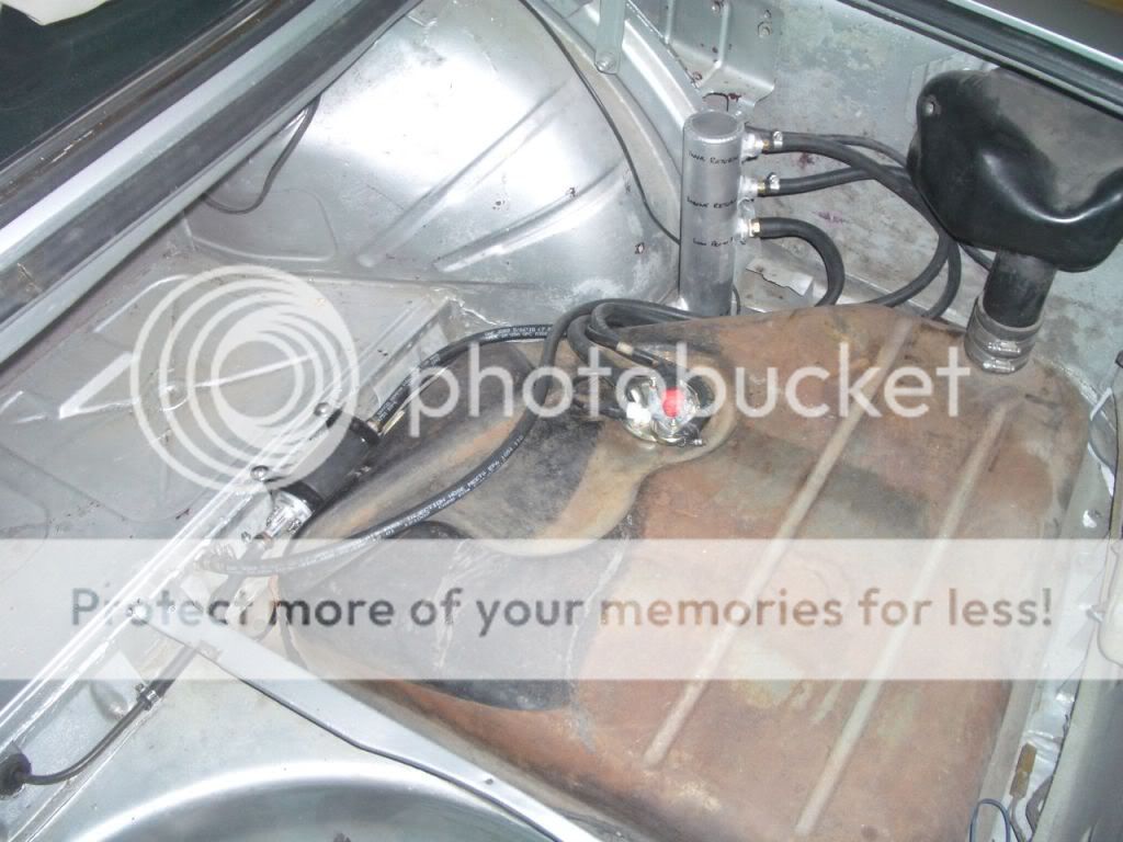
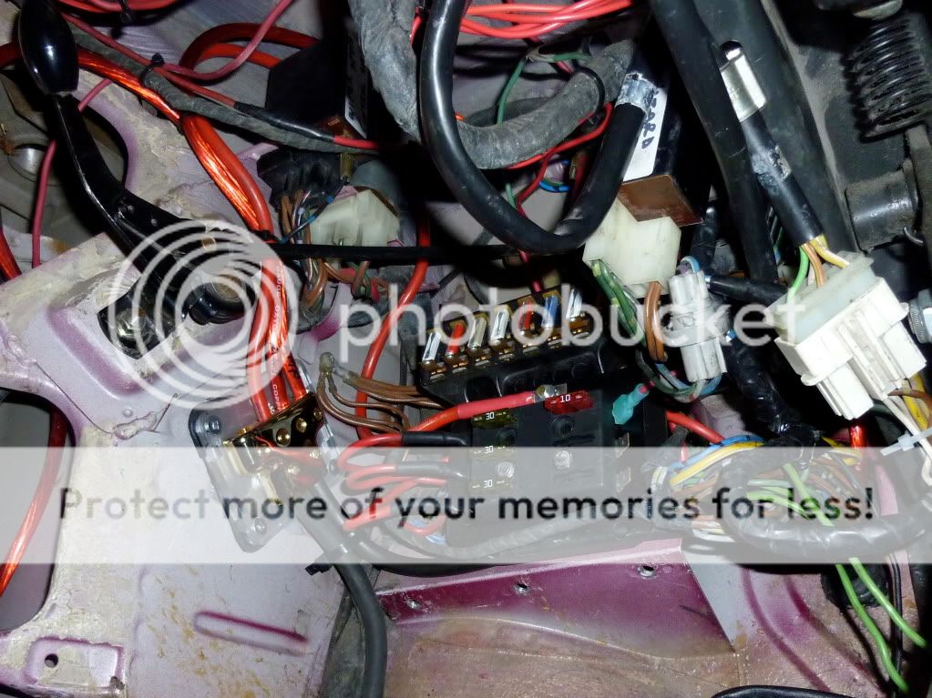
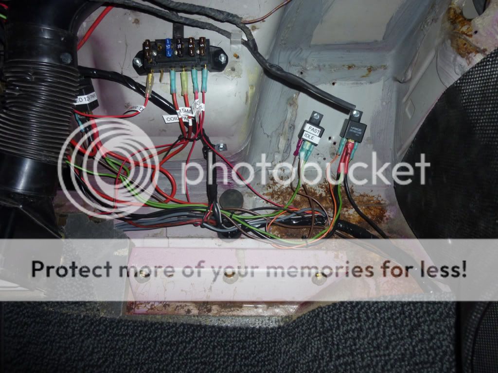
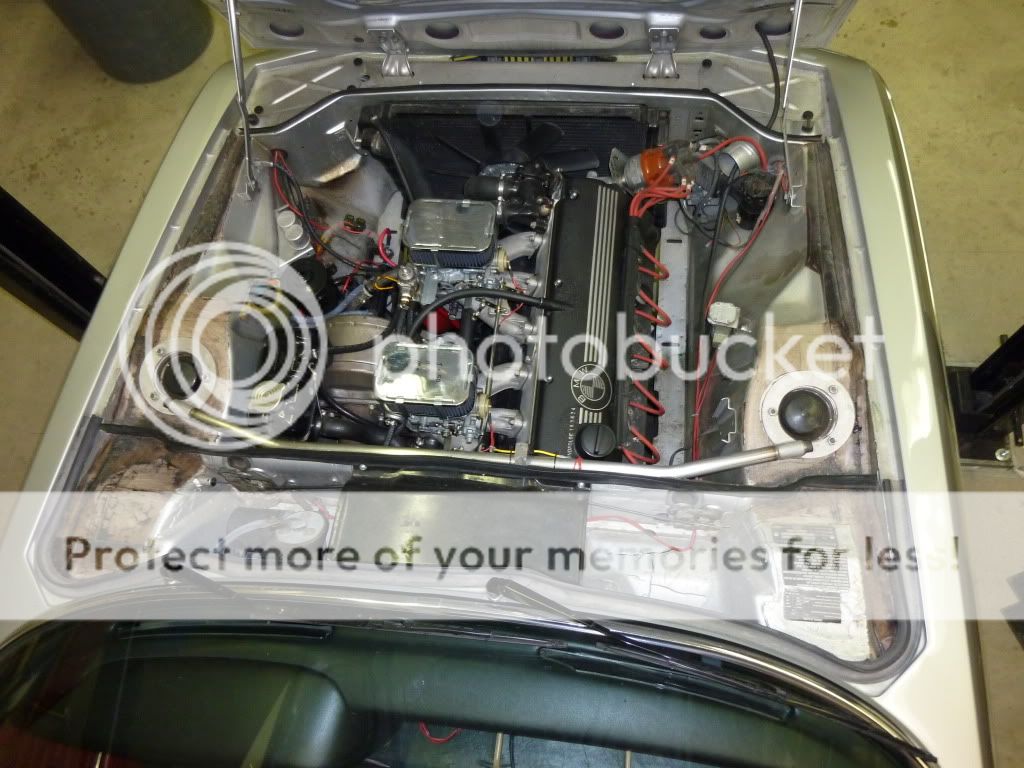
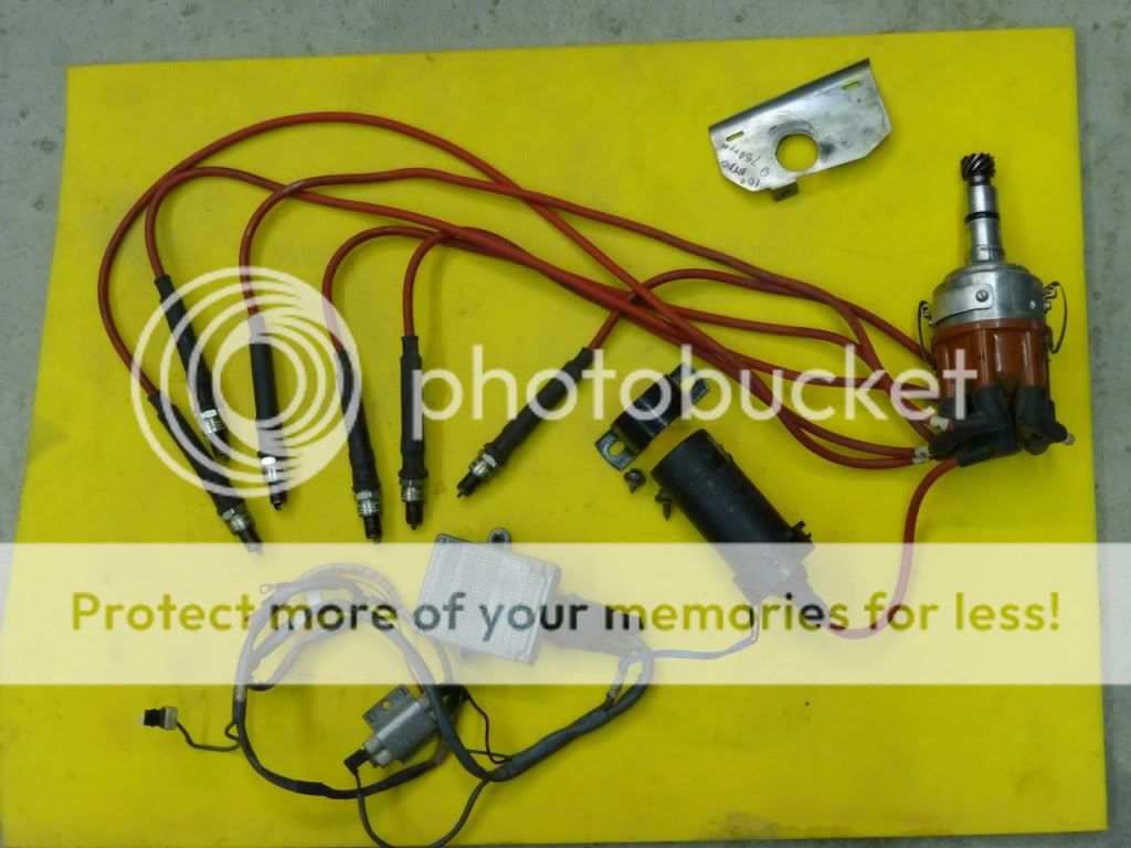
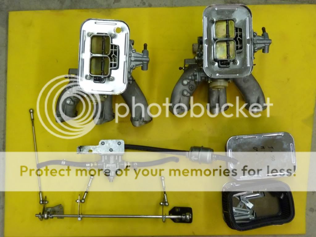
I’m converting my very well sorted twin Weber 38/38 downdraft 3.5l - with a mechanical distributor and 528i engine module - with decent power and very smooth delivery from idle to wide open throttle (yes that was an advertisement for a sale as a package when I’m done) to a fully programmable distrbutorless ignition and EFI system. The car is essentially an early 80’s five series drive train from the fan to the rear diff and OEM stock originality is long gone. It was like that when I bought it and I’ve continued down that path with various small projects (battery under the rear seat, A/C delete, rear seat delete) with a view to reducing the weight of the car and increasing my skill set.
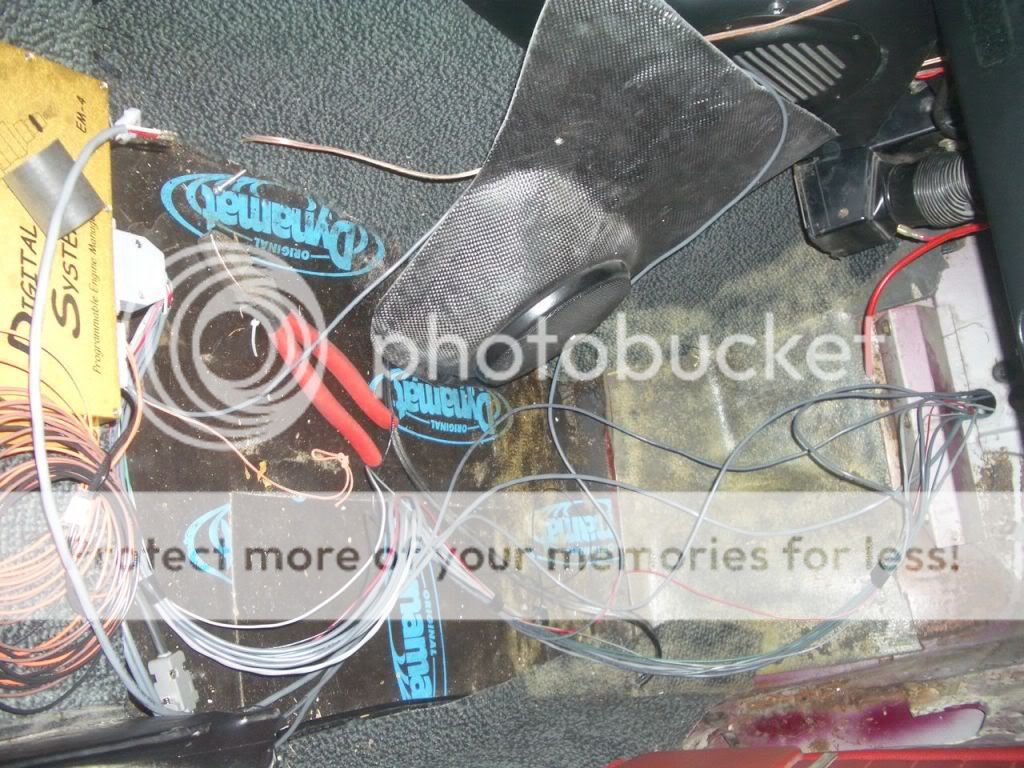
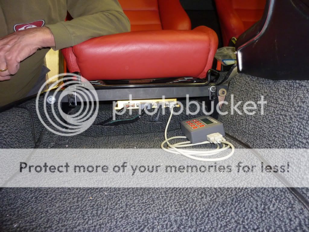
The SDS system is an integrated fuel injection and ignition system. Engine spark timing is fully programmable for both RPM and load (manifold pressure/throttle position). Programming is done with the standard LCD hand held programmer. Triggering is accomplished with magnets attached to the crankshaft pulley and a Hall effect sensor fitted to the timing cover.
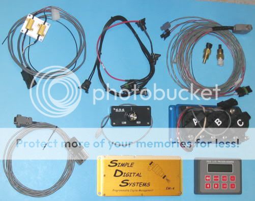
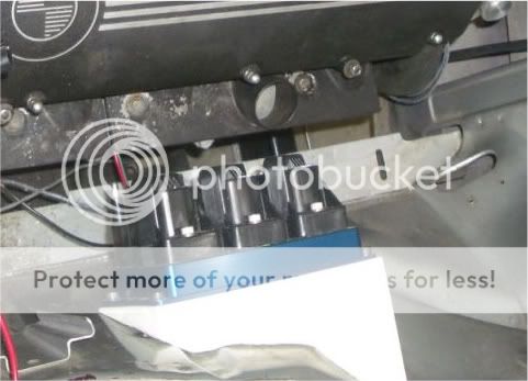
Three triggering magnets are used along with one sync magnet that is used to synchronize the computer with the engine so the computer knows which coil to fire. As each magnet passes the Hall effect sensor, a pulse is sent to the ECU. The ECU determines the exact rpm and manifold pressure, sums the programmed spark retard values and calculates the appropriate delay for the specific conditions at that instant, then triggers each coil to fire at the precise time. Each coil fires two cylinders simultaneously, while one cylinder is on compression, the other on exhaust.
The system measures air temp entering the throttle body (TB) and engine temp in the water jacket and controls start to fast idle to warmup/kick down air/fuel ratio in the ECU so several of the water houses will be eliminated and the ports covered/closed (something to fabricate). A MAP sensor and a throttle position switch provide volume and density of air data to the ECU in order to determine duration of the injector pulse.
For more information (and to correct anything I have misspoken) try http://www.sdsefi.com.
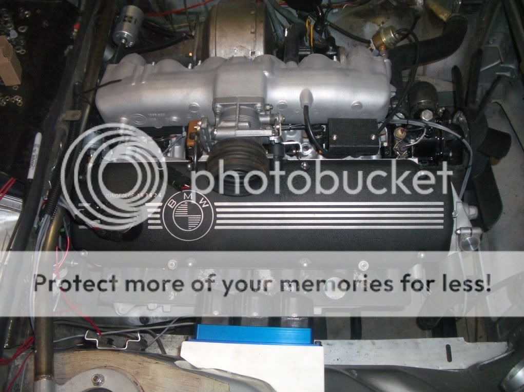
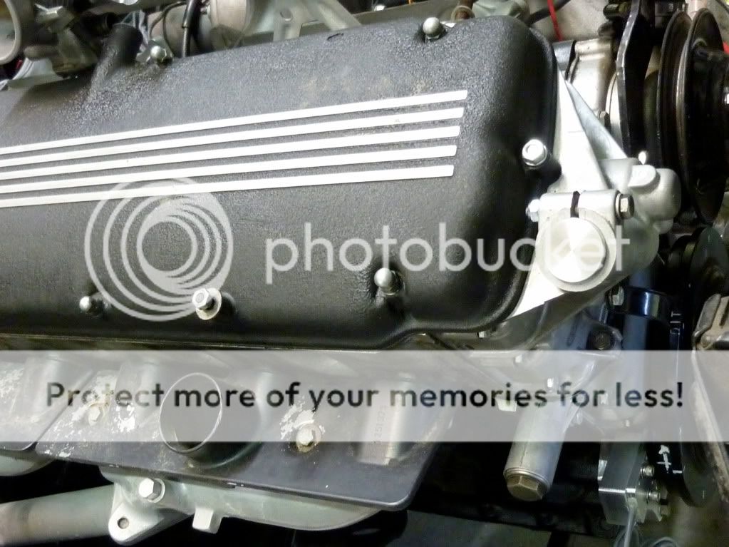
To date, I have gutted the engine of everything that is to be replaced, removed anything that was /is going to be in the way and come up with a bunch of other ideas that will make the task even bigger than I thought it would turn out to be. Typical. Oh, and my life got in the way as well.
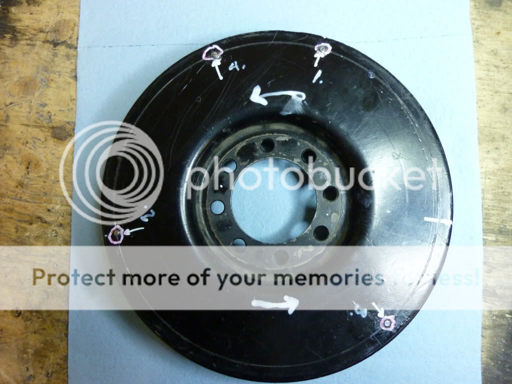
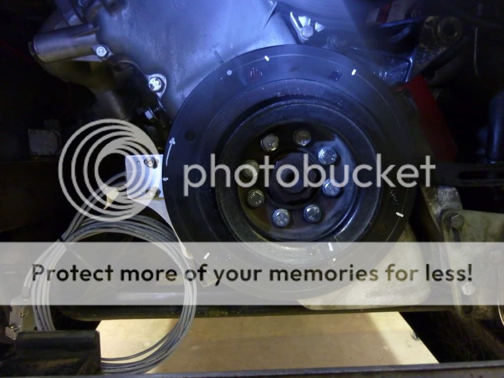
I had to fabricate a bracket to mount the trigger sensor that picks up the magnetic field of 4 magnets in the back side of the engine dampener/crankshaft pulley. The location, spacing, and depth of the holes is precision work so a machine shop took my markings, checked and drilled the holes into which I epoxied the magnets.
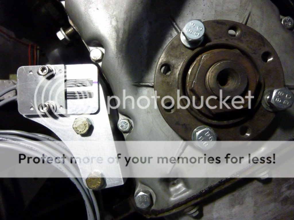
The recommendation for the bracket was to make it strong enough to lift the engine (ie no movement or vibration) so I used ¾” aluminum plate and between the jigsaw, hacksaw, drum sander and files produced a spacer and bracket that bolts into the A/C mounting holes cast into the block. Drilled a couple of holes (measure, measure, measure) in the bracket for the sensor and this is DONE. Almost. Need some final shims to bring the sensor 1.5mm from the magnets.
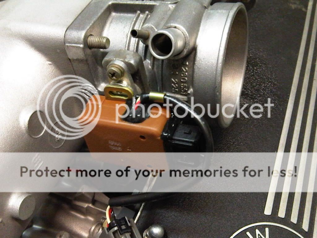
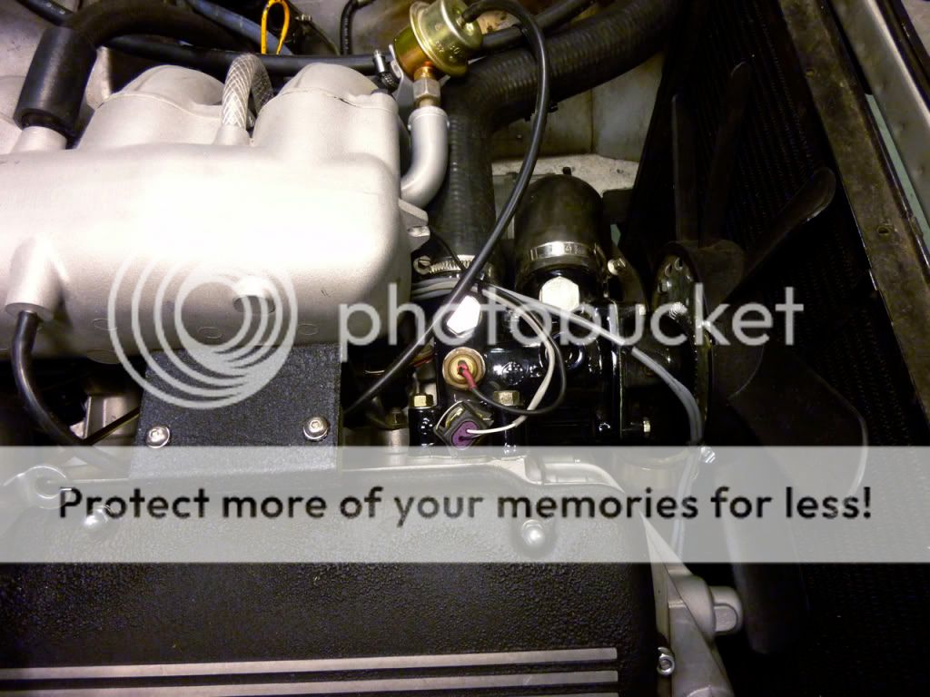
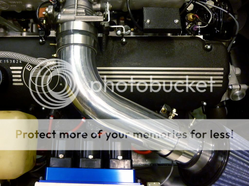
I found a very nice aluminum distributor hole plug meant for 2002 EFI conversions from Tom at http://www.02again.com/ - a perfect fit and nice quality. He also had a TPS Adaptor Plate that was, again, a perfect fit on the throttle body and compatible with the SDS system.
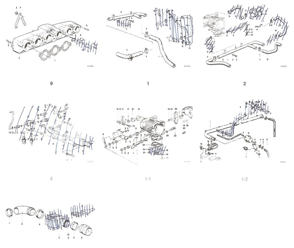
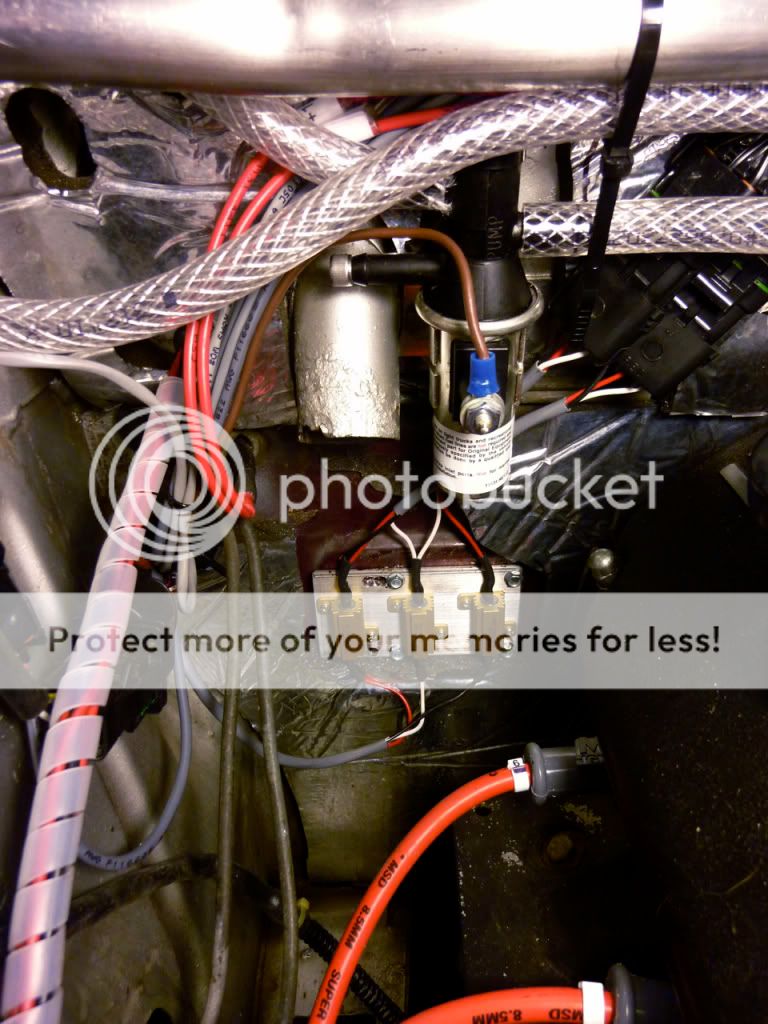
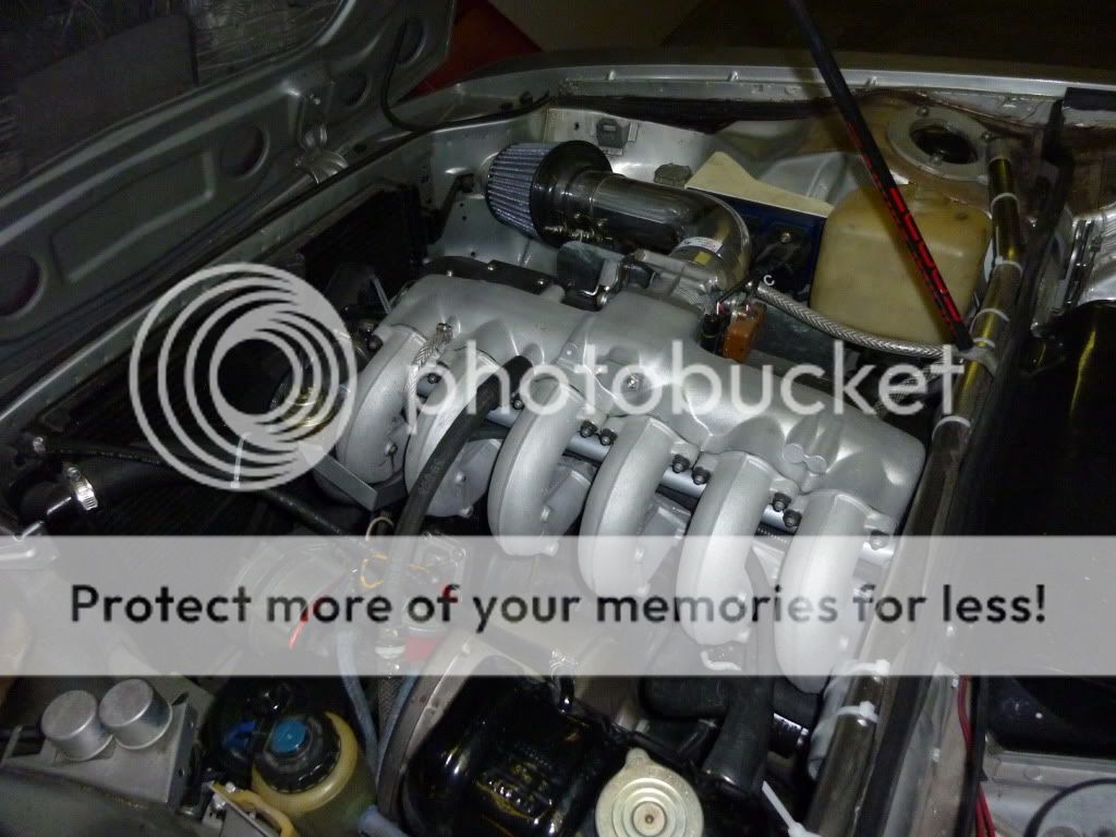
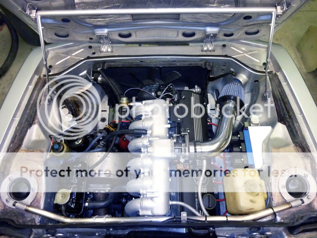
I’ve been doing some dry fitting of the intake components and throttle body to see if there are any issues that need to be resolved (duh) before starting on the fuel delivery system with a La Jolla in tank pre-pump and sending unit , EFI fuel pump, surge tank, fuel lines, injector servicing …. Lot’s of stuff and order more parts.
Sorry about the length. Enough until there is more.
Doug
I’m converting my very well sorted twin Weber 38/38 downdraft 3.5l - with a mechanical distributor and 528i engine module - with decent power and very smooth delivery from idle to wide open throttle (yes that was an advertisement for a sale as a package when I’m done) to a fully programmable distrbutorless ignition and EFI system. The car is essentially an early 80’s five series drive train from the fan to the rear diff and OEM stock originality is long gone. It was like that when I bought it and I’ve continued down that path with various small projects (battery under the rear seat, A/C delete, rear seat delete) with a view to reducing the weight of the car and increasing my skill set.
The SDS system is an integrated fuel injection and ignition system. Engine spark timing is fully programmable for both RPM and load (manifold pressure/throttle position). Programming is done with the standard LCD hand held programmer. Triggering is accomplished with magnets attached to the crankshaft pulley and a Hall effect sensor fitted to the timing cover.
Three triggering magnets are used along with one sync magnet that is used to synchronize the computer with the engine so the computer knows which coil to fire. As each magnet passes the Hall effect sensor, a pulse is sent to the ECU. The ECU determines the exact rpm and manifold pressure, sums the programmed spark retard values and calculates the appropriate delay for the specific conditions at that instant, then triggers each coil to fire at the precise time. Each coil fires two cylinders simultaneously, while one cylinder is on compression, the other on exhaust.
The system measures air temp entering the throttle body (TB) and engine temp in the water jacket and controls start to fast idle to warmup/kick down air/fuel ratio in the ECU so several of the water houses will be eliminated and the ports covered/closed (something to fabricate). A MAP sensor and a throttle position switch provide volume and density of air data to the ECU in order to determine duration of the injector pulse.
For more information (and to correct anything I have misspoken) try http://www.sdsefi.com.
To date, I have gutted the engine of everything that is to be replaced, removed anything that was /is going to be in the way and come up with a bunch of other ideas that will make the task even bigger than I thought it would turn out to be. Typical. Oh, and my life got in the way as well.
I had to fabricate a bracket to mount the trigger sensor that picks up the magnetic field of 4 magnets in the back side of the engine dampener/crankshaft pulley. The location, spacing, and depth of the holes is precision work so a machine shop took my markings, checked and drilled the holes into which I epoxied the magnets.
The recommendation for the bracket was to make it strong enough to lift the engine (ie no movement or vibration) so I used ¾” aluminum plate and between the jigsaw, hacksaw, drum sander and files produced a spacer and bracket that bolts into the A/C mounting holes cast into the block. Drilled a couple of holes (measure, measure, measure) in the bracket for the sensor and this is DONE. Almost. Need some final shims to bring the sensor 1.5mm from the magnets.
I found a very nice aluminum distributor hole plug meant for 2002 EFI conversions from Tom at http://www.02again.com/ - a perfect fit and nice quality. He also had a TPS Adaptor Plate that was, again, a perfect fit on the throttle body and compatible with the SDS system.
I’ve been doing some dry fitting of the intake components and throttle body to see if there are any issues that need to be resolved (duh) before starting on the fuel delivery system with a La Jolla in tank pre-pump and sending unit , EFI fuel pump, surge tank, fuel lines, injector servicing …. Lot’s of stuff and order more parts.
Sorry about the length. Enough until there is more.
Doug
Last edited: