Relays for Front Window Motors

Rek

Well-Known Member
Messages
1,117
Reaction score
355
Location
Islington London England
I wonder whether anyone else has had this issue.

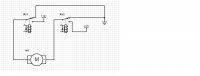
I am putting relays on the front window motors. The motors are the newer E28 rear door kind.

All wired up and nothing happens. Lots of clicks but no movement up nor down.

It seems that the switch, which is a new item, switches full current in one direction but a 0.3 v in the other direction at the same time, tripping the relay both ways so achieving stalemate.

Any ideas on what this might be - are there shoddy switches out there or is it likely to a fault somewhere.
 

jmackro

Well-Known Member
Messages
2,463
Reaction score
728
Location
San Juan Capistrano, Ca.
It seems that the switch, which is a new item, switches full current in one direction but a 0.3 v in the other direction at the same time, tripping the relay both ways so achieving stalemate.

Sorry, but I didn't understand that sentence at all.

My coupe has e28 motors + relays. I wired them as per the diagram below (you need to click on the image to see the whole thing). Is your relay wiring similar to this?
 

Attachments

  • Window motor e24 schematic.jpg
    Window motor e24 schematic.jpg
    62.3 KB · Views: 195
Last edited:

rsporsche

Moderator
Site Donor $$
Messages
10,682
Reaction score
3,711
Location
Atlanta, GA
this is the drawing i created based on information from Stevehose, deQ and i believe Jmackro. i did this drawing for my 2800cs. what you see is 2 relays as Steve has mentioned for 1 motor. the power from the fusebox to the switch just powers the relays. there is power run to flow thru the relay to the motor directly from the battery. hope this helps. i know the colors are bright, but drawing it in autocad and trying to relate to wire colors is not easy

2800cs - window motor rewiring.JPG
 

jmackro

Well-Known Member
Messages
2,463
Reaction score
728
Location
San Juan Capistrano, Ca.
An e28 motor just has two wires; it isn't grounded through its mounting. The schematic that you posted shows the earlier, 3-wire motors. So I'm puzzled how you have your e28 motors hooked up.

The schematic that I posted uses SPDT relays, while the one you posted uses SPST. You need double throw relays to reverse the polarity across the two wires going into the e28 motors to get both up and down operation.

You might want to study the schematic I show in post #2 and compare it to the one in your post #5.
 
Last edited:

rsporsche

Moderator
Site Donor $$
Messages
10,682
Reaction score
3,711
Location
Atlanta, GA
Jay, my wiring diagram is for a 2800cs, no 2 wire motors here. with 3 wire motors, i'm not sure that you need SPDT relays as one side of the motor is powered by one relay, the other side is powered by the other relay. yes ... for e28 motors, the diagram needs to be revised.

the concept is similar to use the switch to power the relay and run power to the switch from the battery to run thru the relay.
 

Layne

Well-Known Member
Site Donor
Messages
292
Reaction score
73
The most likely scenario is that Rek followed directions for a 3-wire motor when hooking up his 2-wire motors. Following the diagram jmacro posted will fix that.
 

jmackro

Well-Known Member
Messages
2,463
Reaction score
728
Location
San Juan Capistrano, Ca.
Jay, my wiring diagram is for a 2800cs, no 2 wire motors here.

Scott:

Sorry - I was thinking that the diagram in post #5 was from the guy (Rek) who started this thread. Rek had said he was using e28 motors, so I thought the 3-wire motor schematic might explain his problem. That'll teach me to read more carefully before replying!

You're right, single throw relays are just fine for the earlier, 3-wire motors.
 

rsporsche

Moderator
Site Donor $$
Messages
10,682
Reaction score
3,711
Location
Atlanta, GA
Jay, the most important thing is that you drew attention to the difference ... so anybody that follows and finds this thread needs to know how to fix the problem ... and you clarified that.
 

Rek

Well-Known Member
Messages
1,117
Reaction score
355
Location
Islington London England
Still not resolved. I am using 2 relays per motor, wired by jmackro's method. My problem is the switch when pushed to lower the windows produces 12+ bolts to the relay which lowers the window, switching that relay and sending the power to the lowering wire on the motor. However, at the same time the lowering button is pushed the raising cable send 0.3 volts to the raising relay which is switching that relay and sending power to the raising input wire of the motor.

The inverse happens when the raising button is pressed.

Whilst the relays were absent it was not apparent as the voltage was via the switch. In this case it was 12+ volts one way and 0.3 volts the other way. Result? The motor worked as the higher voltage won. Adding relays evens the voltage so I have the problem, possibly at the switch.

I hope this explains it better than my first attempt
 

Layne

Well-Known Member
Site Donor
Messages
292
Reaction score
73
You might be using relays that do not have a filter on them. Some have a diode across the coil terminals, some have a resistor (I think a resistor would be better in this case). I had a very hard to solve problem, where the engine would not shut down once running. Turns out the ignition relay I installed had no filter, and the 'noise' from the running coil I suppose (or maybe some other source, I don't know) kept the relay engaged. When the engine wasn't running, the relay switched on and off as it should. Swapping to one with a resistor fixed the problem.
 

Layne

Well-Known Member
Site Donor
Messages
292
Reaction score
73
Look for this symbol on your relay to indicate a filter circuit. Sometimes it's the symbol for a resistor or a diode, can't tell what this one is, but it's there.

relay.jpg
 

jmackro

Well-Known Member
Messages
2,463
Reaction score
728
Location
San Juan Capistrano, Ca.
My problem is the switch when pushed to lower the windows produces 12+ bolts to the relay which lowers the window, switching that relay and sending the power to the lowering wire on the motor. However, at the same time the lowering button is pushed the raising cable send 0.3 volts to the raising relay which is switching that relay and sending power to the raising input wire of the motor.

OK, I get it now. Not sure why .3V shows up at relay X when relay Y is engaged, but I guess it does. And it appears that although these relay coils are rated at 12V, they will engage with as little as .3V (which seems odd to me).

Two ideas:

Add a resistor in series with the relay coil to lower the voltage passing through the relay coil. What value resistor? Well, it depends on how low a voltage will trigger those "12V" relays. I'd start by measuring the resistance of the relay coil and using an external resistor of that value - that will halve the voltage across the relay coil. Be sure to use a resistor of sufficient wattage to handle 6V when the relay is intentionally switched on.

You could also try wiring a diode in series with the relay coil. A diode will provide a .6V voltage drop, and that might work to prevent the relay from triggering with as little as .3V.
 
Last edited:

Rek

Well-Known Member
Messages
1,117
Reaction score
355
Location
Islington London England
I need different relays as Jay mentioned right at the start. I need the relay connections to be earthed, unless activated. That way the relay sending the power closes to send it, and the other relay is still open but earthed, not just open as mine is.

Without the relays, the switch powers one side and earths the other at the same time, making the circuit. I need the relays to do the same.

I am no expert, but I should still apply to The School for the Hard of Thinking. :)
 
Top