Torque Settings

Manual refers to these parts as the trailing link and front axle carrier/crossmember. Neither term is used in the torque setting section for the front axle.
 
Manual refers to these parts as the trailing link and front axle carrier/crossmember. Neither term is used in the torque setting section for the front axle.

24.png


You make an interesting observation. It may be uncommon, but the factory manual evidently amended both its nomenclature and its torque specs - on more than one occasion.

1. Page 31-0/6 (Amendment 3.75) provides for "Wishbone at front axle beam" torque as 60 - 66 ft. lbs.

It appears that in a later amendment, the term "control arm" was substituted for the term "wishbone." Torque specs were amended too.


2. Page 31-0/6 (Amendment 1.76) provides: "Control arm to front axle carrier: 170-190 Nm and 123to 137 ft. lbs." This seems consistent with the 116 ft/lbs mentioned in the 1977 Autobooks edition. Anecdotally, I believe the torque for the type 114 control arm to subframe is approximately 110 ft. lbs.

autobooks_manual_152.jpg
 
So the control arm will be set to 125ft-lbs, but still don't know what to set the trailing link to. Prob self-evident but the engineer in me wants to know.
 
So the control arm will be set to 125ft-lbs, but still don't know what to set the trailing link to. Prob self-evident but the engineer in me wants to know.

Allow me to add to the confusion. Here is a scan of the torque settings found in the "1.76 Amendment." The amendment notation appears on reverse page. Again, different nomenclature.

picture.php


Assume your reference to "trailing link" is "A" below. Not sure that it trails, rather than leads. Have heard it called many things including "braking rod" and "strut" as in "strut to contr. arm and front axle carrier." But that doesn't mean what I hear is correct. It rarely is. Same with what I read. :roll:

HTH

12050001_z.jpg
 
Exactly. I will gestimate the torque based on is removal. I just don't want anything to fail prematurely from over tightening. One would think this also should be tightened under a load like the control arm but nothing other than the CA states ' under normal load".
 
Reopening an old thread, but I’m working on the track rod arm and am confused on what the actual torque settings should be?
Are this the so called clamping bolts mentioned here by MMercurys picture under the steering section?
I do have the blue books, but different words are used for the same thing, but not sure what is correct. 14Nm torque is not much for an M8 bolt as stated here if I’m making the right assumption?
 

Attachments

  • IMG_5051.jpeg
    IMG_5051.jpeg
    266.5 KB · Views: 28
And they're should not been any color between....
Hope you cover contacting area before painting.
Otherwise, remove the paint before you torque the bolts.

Breiti
 
And they're should not been any color between....
Hope you cover contacting area before painting.
Otherwise, remove the paint before you torque the bolts.

Breiti
Interesting point you make here @Breiti.
Indeed the paint needs to not interfere with the tightness. Especially power coat, being a plastic layer, creeps out from under the bolt head (or ring/nut) under pressure from the bolt. Thus reducing the material thickness under the bolt, thus loosening it. But that's theoretically. I've never experienced a bolt come loose, but then I only drove my coupe for 3 years without much tinkering.

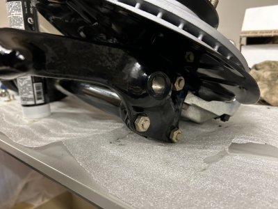
So when you refurbished parts,
How do you practically, and cleanly, keep the paint from not getting where the head/nut /ring sits?

Just a piece of ripped off tape stuck on a bolt hole will not leave a nice clean round edge after paint & pulling it off: how do you do it? Are there special round tape stickers for it?

And then, if I've succeeded to not paint below the bolt/nut, how do I prevent it from starting to rust right there on day 1 on the road?

Is it just something that's "good enough" , and I'm overthinking this ? (Which happens all the time.. i think...)
 
Last edited:
Interesting point you make here @Breiti.
Indeed the paint needs to not interfere with the tightness. Especially power der coat, being a plastic layer, creeps out from under the bolt head (or ring/nut)

How do you practically, and cleanly, keep the paint from not getting where the head/nut /ring sits?

Just a piece of ripped off tape stuck on a bolt hole will not leave a nice clean round edge after paint & pulling it off: how do you do it? Are there special round tape stickers for it?

And then, if I've succeeded to not paint below the bolt/nut, how do I prevent it from rusting there on day 1 on the road?
Is it just something that's "good enough" , and I'm overthinking this ? (Which happens all the time.. i think...)
Very valid question Erik and comment from Breiti. I’ve been doubting about this also. But I count the rust prevention heavier then the risk of loosening bolts in this case. I’ve done it this way with my Fjord e9 and it has never been an issue (checked after few 100km driving) because they are wire wrapped and using loctite I don’t fear the risk in all honesty. Open for other opinions regarding this matter…
 
And then, if I've succeeded to not paint below the bolt/nut, how do I prevent it from starting to rust right there on day 1 on the road?
Wax

Those 3 bolts maybe the most critical bolts at the whole car....

You should don't doubt at my assertion....
You should ask yourself, why at original, those points are machined after coating in the factory.

I just recommended to remove the color.

Breiti
 
Last edited:
Thanks Breiti. Good to know.
And interesting to learn that these points were machined post painting at the factory.
Quite an effort for BMW to machine the paint from those locations post painting.
It shows that it is not only a theoretical risk, but in practice the risk was seen as big enough to warrent the additional work.

I will go ahead and follow your guidance in the critical bolt area's in my rebuild as I progress.
Erik.
 
I just now remember an instance during one of our driving trips with colleagues; all different classic cars, a nice one day tour of Belgium, Germany and NL.
And this Mercedes pagoda of my colleague, just fresh out of an expensive rebuild, just stopped dead on a junction, with each front wheel choosing a different direction.

Who knows, same problem?
 
Back
Top