Need help with Wiring/Relay/Grounds to H1/H4's

Nachtycoupe

Well-Known Member
Site Donor $$
Messages
2,161
Reaction score
1,022
Location
Coeur d'Alene, IDAHO
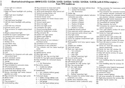
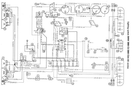
I have spent too many hours with my mechanic at this point working on this (getting very expensive at this point) and need some help from the board. My mechanic is usually very talented and great at diagnosing electrical issues, but this has him stumped too after a lot of sorting, rewiring and troubleshooting. I'll try and explain this as best as possible, electronics is definitely my weak point so bear with me. See attached pics as well of what I am referring too. I also included the 1974 wiring diagram and legend we were using. On that subject, why is there no "high beam relay" in the legend?

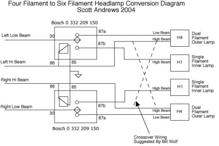
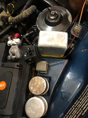
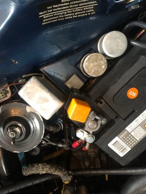
What is happening is, if I don't plug in the orange relay (see pics of it in and out of connection), the low beams work as they should (I call it the central position, normal driving position for the H4/Low beam) and that is where I have it now so I am not high beaming people. If I plug the relay in, all four headlamps light up as if the switch for the head lamps is in the forward position for high beam, but this happens in the central position with relay in. If I pull back as if I were to flash someone with the headlamps it switches to low beam only. I hope I am explaining this right. Sorry if confusing. Normal driving with low beam only should only be the "Outside lights, correct with the H4 that can go from low to high beam. Then high beam the H4 goes to high beam and the center lights (H1's) are only high beam.

If this helps, some background info, when I bought the car the headlamps didn't work and the wires were melted as if improper ground or something. We checked the grounds, relays work, all the lights work and were rewired when installing the H1/H4's, just not as they should. All the lights in the rear work, the little light in the engine bay works and side markers all work. I don't think a simple fuse or none of the lights would work. We looked at the wiring under steering column to the switch and it looks like someone in the past poked the wires and maybe this issue was going on for a while and not properly diagnosed/fixed. The yellow, white and yellow/white wires all look to be in correct positions. The relay in the fuse box area, interior of car works. So, it has been very frustrating. The melted wires were all replaced with new ones, even heavier gauge (I think) so we are scratching our heads at this point.

I pulled the wiring diagrams and legend off of this thread: https://e9coupe.com/forum/threads/wiring-diagram-late-73-75-e9s.22639/

I have a US Spec 1974 3.0CS.

Thanks for any help in advance and if you need more clarity on the issue I will try and explain in more detail. I refer to the issue as being Bass-Akwards -S
 

Attachments

  • IMG_6908.JPG
    IMG_6908.JPG
    293 KB · Views: 43
  • IMG_6909.JPG
    IMG_6909.JPG
    300 KB · Views: 42
  • 74 Wiring Diagram 24x36.pdf
    74 Wiring Diagram 24x36.pdf
    1.3 MB · Views: 32
  • 74 Wiring Legend.jpg
    74 Wiring Legend.jpg
    487.4 KB · Views: 44
The wires were wired fine (I believe). We checked every one. "Just as they should" meaning a white wire was not in the "yellow" wire slot or "yellow/white" not in the wrong prong or whatever the hell it is called. Sorry, again, not versed on all the electronic nomenclature...Meaning he tested the amps or ohms or whatever, and they were all "correct" in the right terminal slots...does that make sense? Sorry if confusing...all these wiring diagrams and nomenclature is like a maze to me...thank you for the question...
 
IF i'm not mistaken, the H4 bulb uses a 3 prong connector where the original sealed beam or H1 lamp uses a 2 prong connector. this looks like a euro wiring diagram and not a USA diagram. this is a USA 3.0cs diagram ... but pre 1974. notice the difference between the low beam and hi-beam and the one you have.

1749243062622.png
 
Hey Scott, thank you for this. I believe the diagram I used is labeled "Later '73-'75 US Spec 3.0CS." So it should be correct, it is from that thread/link I attached. If not maybe it should be relabeled.

Regarding a two prong relay. I never recalled seeing a 2 prong relay on my '73 Bavaria or ever on this coupe. Not saying they don't exist or weren't used but I had H1/H4 on the Bav as well and don't remember a 2 prong? The relay I am using is a four prong with three vertical prongs/connectors and the one horizontal one. I was hoping someone had this exact same situation. I have a feeling we are way overthinking it and it is something stupid/simple. Like right in front of our face but can't figure it out.
 
i am a big proponent of rewiring the headlights and electric windows with power from the battery, using the switches to power relays to turn on the lights / control the window motors. running that much power through the headlight switch or window switches is NOT a great idea

original 2800cs lighting
 

Attachments

I never recalled seeing a 2 prong relay
He's referring to the connectors on the back of the headlights - 2 prong for high beam and 3 prong for low beams (extra filament). Relays will have 4 prongs or 5 prongs if another circuit is on or off when the relay is on or off. Our cars use 4 prong ones: ground & switched 12v, and +12v from battery & whatever it's powering.
 
Last edited:
Shane - The relay is operating backwards, which suggests to me that you have wires in the wrong place.

Two of the four wires in the relay socket go to the switch for the headlights. My best guess would be that you have these two wires crossed in the relay socket.
 
Shane - The relay is operating backwards, which suggests to me that you have wires in the wrong place.

Two of the four wires in the relay socket go to the switch for the headlights. My best guess would be that you have these two wires crossed in the relay socket.
OK, thank you, great stuff! ;)
 
Last edited:
If I can help, I'd be glad to. I am well versed in headlights and relays and such... I have new headlight connectors, new headlight terminals, and new relays and relay terminals that will be helpful in getting the lights working correctly... I am in Colorado, but maybe we can do the work via email? Do you have a camera that will take pictures of the trouble spots for examination?
Andy
 
I picked up a set of perfect Hella H1, H4 lights from an E3 at a wrecker for about $AU40 = $US20
On the coupe I added a relay in the spare slot and connected the low beam wire from the stalk to operate it.
Separated the two low beam wires at the bulkhead and extended each to the relay, so I had a) relay, relieving the upstream switches of excessive load, and b) completely separate load wires to each light.
Used aftermarket H4 sockets - about $4 each.
At the (outer) H4 lamp, installed a relay triggered by the high beam (inner) lamp. When the high beam was off, the H4 low beam was powered by the low beam feed. Turning the high on, it switched the relay so the H4 high beam was powered (by the low feed)
Lights were impressive, and when I checked, all the bulbs that came with the units were 100 watts and putting the lights on high when stationary, the engine revs dipped noticeably. So I've put standard wattage bulbs in.
I used fused relays with a very generous rating for the high and low circuits - I don't want the lights to go out. A perfectionist might protect each bulb's feed separately.
For your entertainment, the car I took the units out of had the lighting wiring joined by simple and poorly-done twists - no solder or mechanical joint.
Adam
 
I agree with @Ohmess . The relay is either switchingincorrectly (as in it is closing when it should open and vice versa) or you have the high beam wires wired to normally closed contact, so when you energize the relay it switches out the high beam
 
First question: are you running fog lamps? If not, then you need a diagram that does not include the wiring, and relay (15), for the fog lamps, as that confuses things a lot.

Your diagram is for a "four filament" system. that would be a low beam bulb and a hi beam bulb on each side. I am not sure about E9's, but in most cases in that situation you want the low beams on when the light switch is pulled, and the hi beams come on when the turn signal lever is moved forward. In "hi beam", all four filaments are on.

The other setup is known as a "six filament" system. Here you use a dual filament H4 bulb in the low beam spot, and a single filament H1 lamp in the hi beam spot.
In this system, when the low beams are on (outside) the low beam H4 filament is illuminated, and the H1 filaments (inside) are out. When the hi beam switch is closed, the inner H1 filaments come on, and the outer H4's switch to hi beam.

I wired this system on my E24 using the diagram below. I 100% endorse @rsporsche 's suggestion to use relays to control all the lights, that vastly reduces the current flowing in the instrument panel and through the light switche(s), and keeps all the high current stuff up front where it belongs.

The diagram posted by @rsporsche is for a simple six filament system. In that one the lo beam relay (16) is controlled by the headlamp switch (wire 26). the hi beams are independently controlled by the hi beam switch (60) via what looks like wire 128. In this system the hi beam and low beam filaments of the H4 bulbs are on at the same time, which generates quite a lot of heat and reduces the life of the lamps. The alternative wiring I posted just above fixes this issue, and controls all of the lamps with relays.
 

Attachments

  • 4To6Conversion.jpg
    4To6Conversion.jpg
    57.1 KB · Views: 21
Last edited:
A quick overview of the electrical stuff in your circuit.
Your orange relay is a simple 4-pin normally open relay. It has the following diagram.
Screenshot 2025-06-15 at 12.26.50 PM.png

Pins 30 and 87 are the controlled pins, and pins 85 and 86 are the controlling pins.

To, for example, control the high beam filaments, pin 30 would go to a fixed current source (for example the output end of a fuse for the lights). Pin 87 would go to the hi-beam filaments. Pin 86 would go to ground, and pin 85 would go to the output of the hi-beam switch.

In operation, when closed, the hi-beam switch will send a small current down the wire to pin 85. This will activate the electromagnet in the relay, and that will then close the connection between pins 30 and 87, causing a larger current to flow to the headlamp filaments.

For completeness, the relay does not care which end (pin 85 or 86) is powered. So, you could also set things up so the hi-beam switch closes the pin 85 wire to ground. If pin 86 is connected to positive battery voltage, then shorting pin 85 to ground will also close the relay. Some cars use this (negative logic) approach to avoid having so many live 12 V wires in the instrument panel.

The entire point of this relay is to provide a higher current switch, and to localize the current up in the front of the car, instead of routing it through all the connectors and wires up to the small contacts in the hi-beam switch. This reduces losses and improves reliability.

Your hi-beam filament wires should connect to pin 87 or pin 30. The other of these should be 12 volts when the key is on (ACC or RUN). Pin 86 0r 85 should be grounded, and the other pin should go to the hi-beam switch. You should be able to test this with a volt meter (if you do not have one, I recommend buying one. it is indispensable), or a test light. connect the volt meter or light between ground and pin 85 of the relay socket. With the key on, and the hi-beams off, you should see zero volts on pin 85. Turn on the hi-beams. Pin 85 shoudl then go to 12 volts. If this doesn't work, then try the same test on pin 86. If either of these is 12 volts with the switch off, then see if it goes to zero when the switch is activated. If this is the case, then the system is using negative logic as described above. In that case, swap pin 86 (or 85, depending on which one is connected to ground) from ground to 12 V.
 
A quick overview of the electrical stuff in your circuit.
Your orange relay is a simple 4-pin normally open relay. It has the following diagram.
View attachment 204061
Pins 30 and 87 are the controlled pins, and pins 85 and 86 are the controlling pins.

To, for example, control the high beam filaments, pin 30 would go to a fixed current source (for example the output end of a fuse for the lights). Pin 87 would go to the hi-beam filaments. Pin 86 would go to ground, and pin 85 would go to the output of the hi-beam switch.

In operation, when closed, the hi-beam switch will send a small current down the wire to pin 85. This will activate the electromagnet in the relay, and that will then close the connection between pins 30 and 87, causing a larger current to flow to the headlamp filaments.

For completeness, the relay does not care which end (pin 85 or 86) is powered. So, you could also set things up so the hi-beam switch closes the pin 85 wire to ground. If pin 86 is connected to positive battery voltage, then shorting pin 85 to ground will also close the relay. Some cars use this (negative logic) approach to avoid having so many live 12 V wires in the instrument panel.

The entire point of this relay is to provide a higher current switch, and to localize the current up in the front of the car, instead of routing it through all the connectors and wires up to the small contacts in the hi-beam switch. This reduces losses and improves reliability.

Your hi-beam filament wires should connect to pin 87 or pin 30. The other of these should be 12 volts when the key is on (ACC or RUN). Pin 86 0r 85 should be grounded, and the other pin should go to the hi-beam switch. You should be able to test this with a volt meter (if you do not have one, I recommend buying one. it is indispensable), or a test light. connect the volt meter or light between ground and pin 85 of the relay socket. With the key on, and the hi-beams off, you should see zero volts on pin 85. Turn on the hi-beams. Pin 85 shoudl then go to 12 volts. If this doesn't work, then try the same test on pin 86. If either of these is 12 volts with the switch off, then see if it goes to zero when the switch is activated. If this is the case, then the system is using negative logic as described above. In that case, swap pin 86 (or 85, depending on which one is connected to ground) from ground to 12 V.
Scott - I agree this is a good discussion of how the standard Bosch relay works. However, if you look at the wiring diagram for Shane's car, terminals 85 and 86 run to the light switch. And functionally, when you initiate the brights the circuit (if operating properly) not only sends power through terminal 30 to terminal 87 (which is wired both to the high beam filament and to one of the low beam filaments), it also cuts power to the low beam filament that is used when the brights are not on. That low beam filament cut off must happen at the light switch. A multimeter check on terminals 85 and 86, therefore, will only find a path to ground when the brights are on, because turning on the brights initiates the relay to cause a connection between terminals 30 and 87. From Shane's description, installing the relay makes a connection between terminals 86 and 87 when the brights are not switched on, which means either terminal 85 or 86 is grounded when it shouldn't be.
 
Scott - I agree this is a good discussion of how the standard Bosch relay works. However, if you look at the wiring diagram for Shane's car, terminals 85 and 86 run to the light switch. And functionally, when you initiate the brights the circuit (if operating properly) not only sends power through terminal 30 to terminal 87 (which is wired both to the high beam filament and to one of the low beam filaments), it also cuts power to the low beam filament that is used when the brights are not on. That low beam filament cut off must happen at the light switch. A multimeter check on terminals 85 and 86, therefore, will only find a path to ground when the brights are on, because turning on the brights initiates the relay to cause a connection between terminals 30 and 87. From Shane's description, installing the relay makes a connection between terminals 86 and 87 when the brights are not switched on, which means either terminal 85 or 86 is grounded when it shouldn't be.
Sounds like something is not wired correctly... my understanding of this type of relay is:

85 should be grounded (permanently)
86 should get power when you want the load to be energized (headlights ON)
87 is power OUT to the load... (may go through the fuse box, before or after the relay)
30 is 12V power IN to the relay, usually from the battery (thick red wire).

Not sure why the wire from 85 is run to the light switch, this should be run to the nearest convenient ground point.
86 should run to the light switch to energize the lights.
Terminal 30 should be getting power from the BATTERY, not the light switch.
I'd rethink the whole lighting circuit...
Be glad to have a stab at solving it with one ask- a detailed list of related WIRING that appears to be stock, their COLORS, and what TWO POINTS they run between. For starters, headlight wires should be brown (ground), yellow (LOW beam), and White (HIGH beam).

I do plenty of headlight wiring and relay work on vintage BMWs, starting with my 1972 2002's (Amplilux headlights)... and my 1986 535i with separate high and low CSR headlights (4 light system). They all work perfectly, despite the original factory wiring... be glad to provide details if you would like- just ask.
Andy
 
Hey guys, sorry for the delay in responding. Thank you all for contributing to the conversation. The more I read, the more confused I am getting but this is great stuff for my guy to digest and understand more what is going on. He is a very bright guy and I know he is losing sleep over this as he did many checks but obviously still something wrong. I am going to send him the link to this thread as I had no idea you guys have been so generous with your time and knowledge about this situation. This is why I told Arthur, "I hate electrical issues." LOL...if I think it is one thing, it is usually the opposite. We will definitely figure this out now once he goes through all the comments. I will report back what it was when (not if) we finally figure it out. Any other ideas are welcome...thanks again crew!
 
Good start, anyway. Give our best wishes to your guy...
I will, he will like that, thank you, he is a great guy and I'm lucky to have him here in Northern Idaho, one of the few younger guys that prefers working on older German European and British cars (and not afraid of carbs)!
 
Scott - I agree this is a good discussion of how the standard Bosch relay works. However, if you look at the wiring diagram for Shane's car, terminals 85 and 86 run to the light switch. And functionally, when you initiate the brights the circuit (if operating properly) not only sends power through terminal 30 to terminal 87 (which is wired both to the high beam filament and to one of the low beam filaments), it also cuts power to the low beam filament that is used when the brights are not on. That low beam filament cut off must happen at the light switch. A multimeter check on terminals 85 and 86, therefore, will only find a path to ground when the brights are on, because turning on the brights initiates the relay to cause a connection between terminals 30 and 87. From Shane's description, installing the relay makes a connection between terminals 86 and 87 when the brights are not switched on, which means either terminal 85 or 86 is grounded when it shouldn't be.
Not sure I follow, or agree. First off, which relay are you referring to? I assume this is 18, the low beam relay. Pin 86 goes to the low beam light switch, but 85 goes to ground (brown wire). Pin 30 goes tot he battery via fuse 6. Pin 87 goes to the low beam filaments. Power to the low beam switch is fed through the main light switch 63. The low beam switch also has a white wire (#1272) that goes to the high beam filaments. This also visits pin 85 or 86 (can't really read it) of the fog lamp relay 15. The other coil pin on that relay goes to the fog lamp switch, which GROUNDS that pin when the fog lamps are on. I assume this means that the fog lamps only come on when the hi beams are on.

[CORRECTION: See additional post below. The fog lamps sth does not ground the other side of the relay. It actually powers it. So, if the high beams are off, current flows through the relay coil illuminating the fog lamps, but when the hi beams are on, both sides of the fog lamp relay coil are at 12 volts, so it opens and the fog lamps go out. ]

Here is an annotated diagram.
Screenshot 2025-06-16 at 12.19.39 PM.png
 
Last edited:
Back
Top