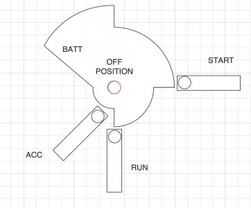
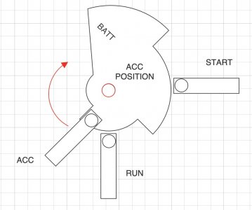
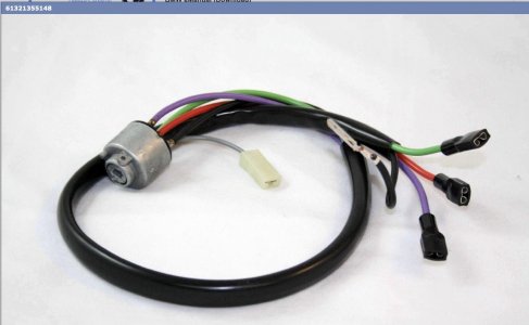
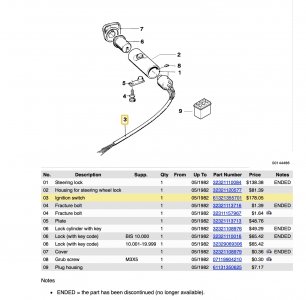
I recently acquired my 2800CS and it has an add on ignition switch using a secondary key. I wanted to get the original key working and was planning to use the original switch as a template to create an alternate. Unfortunately, my car apparently did not come with the original. I've tried to get started by making sample parts of differing sizes but Im at a point where real dimensions would be helpful. I have a switch that does fit and turns but its sloppy and some items like the set screw tab I can't easily size. So, I'm coming here to ask if someone can provide dimensions for the ignition switch. Besides the dimensions I also have a few questions. When I turn my key I don't get any tactile feed back like a click for each position and a spring push back for the starter position. Are these provided by the switch or do I have something else defective or missing? The steering lock where the switch mounts does exist in my car so my assumption is that the switch needs detents and a spring.
These are the dimentions I'm looking for.

A. Body diameter
B. Smaller diameter containing the key
C. Length of the body
D. Length of the smaller diameter with key
E. Height of the pin
F. Height of the set screw flange
G. Width of the set screw flange
H. Diameter of the pin
I. Diameter of the key hole
J. Width of the key hole
K. Width of the small side of key hole
L. Width of the larger side of key hole
M. Depth of the set screw flange
N. Distance from outside switch to pin
O. Distance from outside switch to set screw flange
P. Diameter of center key hole
Q. Distance to set screw
Theta. Angle from center pin to center set screw flange
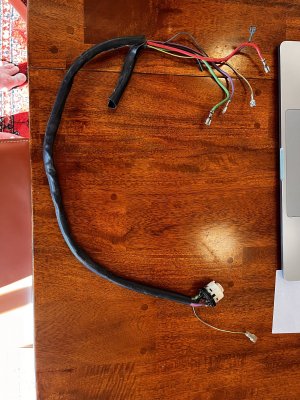
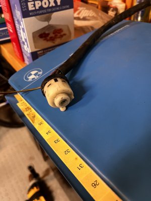
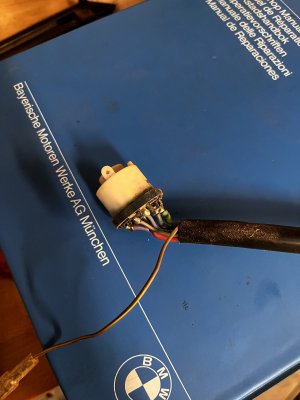
Here are my experiments so far. I also have a circuit ready but I need to finish the boards. The switch works by using magnets to trigger the 4 positions. Then an external board with 4 relays will provide the power like the original switch.


These are the dimentions I'm looking for.
A. Body diameter
B. Smaller diameter containing the key
C. Length of the body
D. Length of the smaller diameter with key
E. Height of the pin
F. Height of the set screw flange
G. Width of the set screw flange
H. Diameter of the pin
I. Diameter of the key hole
J. Width of the key hole
K. Width of the small side of key hole
L. Width of the larger side of key hole
M. Depth of the set screw flange
N. Distance from outside switch to pin
O. Distance from outside switch to set screw flange
P. Diameter of center key hole
Q. Distance to set screw
Theta. Angle from center pin to center set screw flange
Here are my experiments so far. I also have a circuit ready but I need to finish the boards. The switch works by using magnets to trigger the 4 positions. Then an external board with 4 relays will provide the power like the original switch.