Electrical Issue

Tom P

Well-Known Member
Messages
159
Reaction score
10
Location
Vacaville, CA
Hi there,

It's been a while since posting but glad to be back and especially glad to see a thriving E9Coupe.com board. I'm reaching with an electrical issue that I seem to have caused myself.

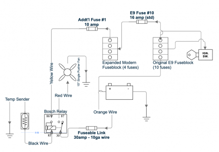
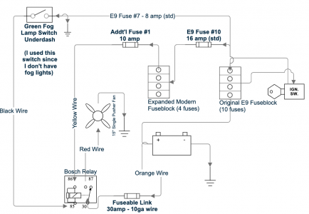
Despite installing and using an electric pusher fan successfully for many years, the temp sensor recently failed on me causing the fan to unknowingly stop working resulting in my coupe overheating. The fan was fused inline and powered through a relay triggered by a temp sensor located on the water pump housing. Not wanting to be surprised by a failed sensor again, I felt that a seemingly simple solution would be to remove the sensor and just run the fan full-time going forward. So, I plugged the sensor hole but decided to run the sensor "trigger" wire to my unused, green fog light switch under dash as a stealth way to turn on/off the fan if ever needed. I felt this was safe due to the low amperage needed to trip the relay. This worked well until about my 3rd outing when the fan stopped working. I checked the fuses and see that the inline fan fuse burned and my fuse 7 burned as well.

I removed the fan wiring to isolate that component and then using a test light w/probe (and no fuses installed in my fuse block), I see that my D+ blue wire lead at my unused voltage regulator socket lights up. My fuel pump wire light up at the pump, my lower tabs on fuse block at fuse 1, 2, 3, 6, and 7 light up (# 6 lights up very dimly and illuminates the red "L" indicator on my dash), and I'm not getting any lights when the upper tabs are probed (although an under dash relay is triggered when upper 6 and 7 tabs are probed - but no light).

So, I'm concerned there's a ground fault somewhere but thankfully not seeing any burned wires anywhere. Any ideas where to look next?

Thank you!
 
Don't look in your fuse box in your dash- that's for sure. Running 40 amps for an auxiliary fan will toast a box designed for 25 amps.

I have to say- running a cooling fan all the time is not good for your engine. Time to install a new temp sender perhaps. Fused from a relay good for 40 amps direct from battery. Do you have AC?
 
Thanks Don, yes, running AC as well. FYI, my inline fan fuse from battery direct was 30 amp on heavy guage wiring paired with lightweight temp sensor wiring to the relay (that I subsequently re-routed to the switch recently). That set up worked well for years before being tripped up last week!
 
I have a question on how you are conducting your test, and then a bunch of comments.

With the test probe, are you testing continuity to ground?

Now, on to the comments:

First, as to the 40 amp fuse comment Don made, he is not exagerating. Look closely at my fuse block at fuse number 1. The high school dropout who wired the stereo for the prior owner of my car installed a big ass amplifier, pulled the existing fuse and installed a 40 amp fuse in its place. When the prior owner cranked the tunes, she melted the fuse block, the wiring underneath the fuse block, and the wiring at both front and rear running lights on the left side of the car. The first few months of ownership of my car were spent addressing these issues.

IMG_0680.JPG


Second, if you are doing circuit tracing at the fuse block, you need to understand the connections at the back of the fuse block. This picture is from a 72 - later cars are a little different - but this shows that the solid red area behind fuses 4 & 5 incorporates six spade lugs (one has a fat red wire and another has a fat black wire) that are all tied together. These distribute unswitched power. Similarly, fuses 6 & 7 are connected, and have three spade connectors, all of which have solid green wires attached to them on this block. These distribute switched power. These distribution connections are illustrated in the wiring diagrams, but you have to look really closely to see them.

Fuse Block.jpeg


You can also see the downstream connections here. You mentioned that you blew fuse 7. There is one connection on this fuse block on the downstream side of fuse 7, with three green and white wires connected to it. The three circuits connected by this one connector will be electrically connected by this one wire connection. Here again, this is shown in the wiring diagrams, but you need to look really closely to see it. So, if you are testing for continuity to ground at the fuse block, and you have continuity in any one of three circuits connected together at fuse 7, you will find continuity to ground at the downstream connector. (This may not be exactly the same as your car - use the wiring diagram in your owners manual to identify the circuits in question.)

So, the original fan relay had switched power to one side (85 or 86) and the ground side goes to the temp sender. The sender then provides a path to ground at a specified temperature. The fog light switch is designed to provide switched power to the fog lights, which are grounded to the front bumper. Did you wire the switched power side of the fan relay to the fog light switch, and the ground the other trigger side? If so, where did you pick up switched power? Or alternatively, did you run the ground wire that had been running to the temp sender to the fog light switch, with the other side of the switch to ground?
 
Hi Chris, thank you for such an awesome summary / analysis. Allow me to digest it and then I'll share with you how I had initially wired it and then how I re-wired it to hopefully offer more clues on what may have gone wrong. Thank you again...
 
If it were me...

I'd back all the way up to how the cooling system is working first. My E3 was running a little warm on hot days so I thought I'd add an electric pusher fan in addition to the water pump fan. But I also found my original radiator was in poor shape so I replaced it with a new aluminum one. Another member on this site questioned why I needed a pusher fan since a stock cooling system should work fine. I put it on anyway with a temp sensor.

I live in the Sacramento area were it gets really hot, running a M30B35 3.5L motor and since changing the radiator the electric fan has never come on.

I don't have AC, so with your car you might make sure your cooling system is working the way it should and wire the pusher fan to come on with your AC. It shouldn't need anything more than that.

Dan
 
Hi there, thanks Dan x2. To give you a sense for how I wired it originally, here's a rough schematic. This worked well for many years until the temp sensor failed. I'll post another schematic next to show how I rewired it without a temp sensor.
 

Attachments

  • Screenshot 2024-08-21 at 11.44.54 PM.png
    Screenshot 2024-08-21 at 11.44.54 PM.png
    95.1 KB · Views: 28
And here's how I rewired the Temp Sensor wire to the Fog Light switch instead to allow for manual fan on/off control. It worked well a few times and then failed with a blown Fuse #7 and a blown 30amp fusible link (unsure which blew first). All other wiring appears intact. Relay tests OK. Fan tests OK. Fog Light switch tests OK. Fuse #7 blows immediately when ignition is turned on (even after removing all wiring to the fan).
 

Attachments

  • Screenshot 2024-08-22 at 12.45.34 AM.png
    Screenshot 2024-08-22 at 12.45.34 AM.png
    110.7 KB · Views: 22
Thanks Dan, there seems to be a number of ways to achieve the same result! Mine worked well for about 10yrs before the sender failed. Now, my "fix" to remove the sender and wire in the manual switch instead has failed as well. Wishing I just replaced the sender! I'm checking for a ground fault on fuse line 7. It's just weird to me since my switch just needs to carry enough current to flip the relay. Any other thoughts?
 
I have a question on how you are conducting your test, and then a bunch of comments.

With the test probe, are you testing continuity to ground?

Now, on to the comments:

First, as to the 40 amp fuse comment Don made, he is not exagerating. Look closely at my fuse block at fuse number 1. The high school dropout who wired the stereo for the prior owner of my car installed a big ass amplifier, pulled the existing fuse and installed a 40 amp fuse in its place. When the prior owner cranked the tunes, she melted the fuse block, the wiring underneath the fuse block, and the wiring at both front and rear running lights on the left side of the car. The first few months of ownership of my car were spent addressing these issues.

View attachment 187896

Second, if you are doing circuit tracing at the fuse block, you need to understand the connections at the back of the fuse block. This picture is from a 72 - later cars are a little different - but this shows that the solid red area behind fuses 4 & 5 incorporates six spade lugs (one has a fat red wire and another has a fat black wire) that are all tied together. These distribute unswitched power. Similarly, fuses 6 & 7 are connected, and have three spade connectors, all of which have solid green wires attached to them on this block. These distribute switched power. These distribution connections are illustrated in the wiring diagrams, but you have to look really closely to see them.

View attachment 187897

You can also see the downstream connections here. You mentioned that you blew fuse 7. There is one connection on this fuse block on the downstream side of fuse 7, with three green and white wires connected to it. The three circuits connected by this one connector will be electrically connected by this one wire connection. Here again, this is shown in the wiring diagrams, but you need to look really closely to see it. So, if you are testing for continuity to ground at the fuse block, and you have continuity in any one of three circuits connected together at fuse 7, you will find continuity to ground at the downstream connector. (This may not be exactly the same as your car - use the wiring diagram in your owners manual to identify the circuits in question.)

So, the original fan relay had switched power to one side (85 or 86) and the ground side goes to the temp sender. The sender then provides a path to ground at a specified temperature. The fog light switch is designed to provide switched power to the fog lights, which are grounded to the front bumper. Did you wire the switched power side of the fan relay to the fog light switch, and the ground the other trigger side? If so, where did you pick up switched power? Or alternatively, did you run the ground wire that had been running to the temp sender to the fog light switch, with the other side of the switch to ground?
Hi Chris,
Thanks again for your write up. Been reviewing it and to answer your questions, I was running a single post temp sender above my water pump. The ground was the sender itself to the block. When that failed, I took the sender wire and moved it to switched power on Fuse #7 via a lead on my unused Green Fog Light Switch. I simply removed one of the existing leads on that switch and replaced it with the single lead from the temp sender. I tested it and it worked fine. My thinking was that I just need enough power to flip the relay. Being that it was switched and fused, I felt it was a safe approach. A few days later I couldn't start the car. Fuse 7 had blown causing my fuel pump to be inoperable. Fuse 7 now pops immediately when ignition goes to on position. Now working backwards as Dang suggests to find the issue! I still feel good about how I wired it. Would you agree or did I completely miss the boat here? Thank you!
 
I was running a single post temp sender above my water pump. The ground was the sender itself to the block.
Tom,
If the wire to the sender went to ground thru the sender, then you should have just grounded the sender wire to see if the fan worked. The relay must have been getting +12V from the other side of the relay.
Am I understanding that correctly?
Dan
 
Tom,
If the wire to the sender went to ground thru the sender, then you should have just grounded the sender wire to see if the fan worked. The relay must have been getting +12V from the other side of the relay.
Am I understanding that correctly?
Dan
Thanks Dan, you make an interesting observation. Please excuse me if I didn't put the ground on the right side of the switch. It should probably be on the left side of the switch now that I look at the schematic.

Here's my logic and please understand the sender was removed from the equation and in it's place is my green fog light switch. Typically, ignition is turned on, fog light switch is normally open and has power when needed. When the fog light switch is pressed, it becomes grounded due to the ground wire to the switch and the fog lights light up. So, my logic was, remove the sender, take the sender wire and simply attach it to the switch in lieu of the fog light wiring. When I press the switch, the circuit is then closed due to the ground wire on the switch and then the fan turns on. That worked beautifully only but a few times before Fuse 7 popped and my fusible link melted.

Does this make logical sense? Or do you see a flaw in my "fix"? I'm starting to believe there was a coincidental other failure somewhere in my circuit. For the fusible link to fail, that line had to get really hot. This makes me think my fan failed. I've since tested it with power and ground and it does turn - just wondering if it's binding somehow. I tested my relay and it's working fine too. I'm puzzled! Thanks again for thinking this through with me.
 
Tom,
If the wire to the sender went to ground thru the sender, then you should have just grounded the sender wire to see if the fan worked. The relay must have been getting +12V from the other side of the relay.
Am I understanding that correctly?
Dan
The image you copied shows how I solved for the bad temp sender. Here's how I had it wired when I was using the temp sender before that device failed. Hope this helps show you my before / after.
 

Attachments

  • Screenshot 2024-08-21 at 11.44.54 PM.png
    Screenshot 2024-08-21 at 11.44.54 PM.png
    95.1 KB · Views: 18
Tom:
Please look at what @2000CS added. Per your schematic you have positive on both sides of the switch. The switch should only go to ground for the relay to work. That is Black on one side of the Green Switch and Ground on the other. That is UNLESS the wire from "Fuse #7" is ONLY for the switch light which doesn't seem to show.
Dan
I was typing this same thing when Dan posted. Your diagram shows that you not only wired the relay pin 85 to fuse 7 as stated in your post, you also wired it to ground which you did not say. This will immediately cause fuse 7 to blow when you depress the fog light switch.

Your circuit would work if you removed the wiring from the fog light switch to fuse 7. But then again, you should not run the fan all the time, and remembering to turn it on and off is not a good procedure. Best to replace the temp switch. They are simple, robust and cheap. Dan's excellent thread linked above shows you can get one for $12 (maybe a little more now.)
 
Ahh, I think I see it now. By using the switch I took away my ground line to relay lead 85. If I want to use a switch, I would need a switch to ground, not a switch to power. Is that what you are saying? My logic was that the fog light switch was grounded but by flipping the switch, I'm creating a circuit to send power through it instead of ground through it. Is that right? If so, I'll get to work and clean it all up. I do agree, it would be nice to just rely on the temp sender so I'll rebuild it that way. Thank you all for looking at this closely for me, it's much appreciated. More to follow soon.
 
Back
Top