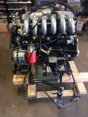
Engine and front suspension carrier install from bottom, what gotchas???

jjs2800cs

Well-Known Member
Messages
286
Reaction score
105
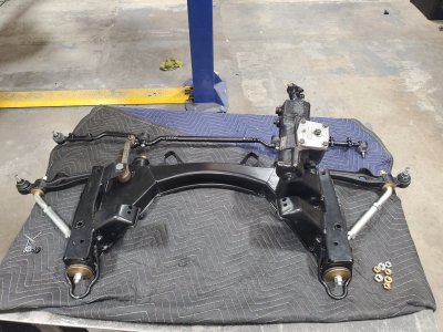
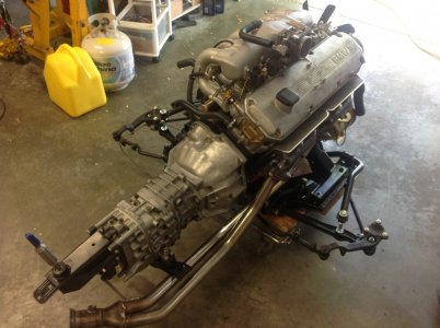
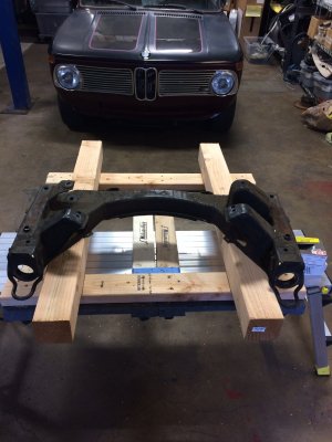
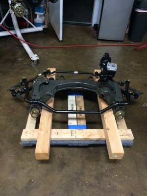
We are thankfully getting close to installing the engine/tranny assembly. We have a lift so the entire assembly came out from the bottom of course with the front suspension carrier.

When we removed it, all the accessories, ps pump, alternator, AC compressor, etc had already been removed, Plus both intake and exhaust manifolds were off. So other than the trick of uncoupling the steering from the box, it was fairly straight forward, albeit a little scary, well maybe more than a little scary when first lifting the car body.

However, going back in we would like to install as much "stuff" as possible before hand. Reasoning is with fresh paint, why risk any damage say installing the exhaust manifold, etc. lift over the fenders plus the ease of installing components on the floor.

So what experiences and gotchas have others had in doing so. We did watch Peter's video and it looked like he pretty much had everything already on, save the carbs.

jjs2800cs
 
Peter has been pretty quiet here lately, but he's the guy I would suggest you ask about this. He's done it a couple of times. I recall selling him a steering column shaft because he bent one.
 
I would leave compressor, Alt and PS off, they are easy to install once motor is in but they would fit I think.
 
It all works from the bottom. As mentioned, the difficult part is the steering box to column.

If you have the column out of the car then just bolt everything to the subframe and lift that sucker up in there. Four bolts and you're done. Basically.

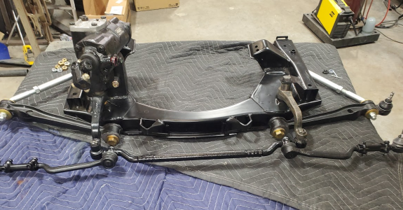
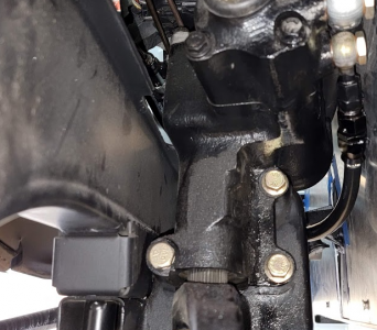
But if the column is in the car I would suggest installing the steering box (u-joint) to the column first. You can even connect the p/s hoses to the box too while everything is separated. Install the pitman arm onto the box first, disconnected from the drag link. Suspend the box in roughly the correct location, then lift the subframe w/ motor et all up into the bay and install the 3 bolts to attach the steering box to the subframe. The bolts aren't that tough to reach. Insert drag link into pitman arm, castle net, cotter pin, etc.

I just find it hard to get the splines and flat section on the column lined up and u-joint spread enough and then enough leverage to get that column and u joint married when the movable part is the entire motor and subframe. If the moveable part is just the column (and the brake booster/master isn't in the way), then marrying the column to the box is doable later.
 

Attachments

  • Not this way.png
    Not this way.png
    1.2 MB · Views: 194
  • the three bolts.png
    the three bolts.png
    506.2 KB · Views: 189
Last edited:
It all works from the bottom. As mentioned, the difficult part is the steering box to column.

If you have the column out of the car then just bolt everything to the subframe and lift that sucker up in there. Four bolts and you're done. Basically.

But if the column is in the car I would suggest installing the steering box (u-joint) to the column first. You can even connect the p/s hoses to the box too while everything is separated. Install the pitman arm onto the box first, disconnected from the drag link. Suspend the box in roughly the correct location, then lift the subframe w/ motor et all up into the bay and install the 3 bolts to attach the steering box to the subframe. The bolts aren't that tough to reach. Insert drag link into pitman arm, castle net, cotter pin, etc.

I just find it hard to get the splines and flat section on the column lined up and u-joint spread enough and then enough leverage to get that column and u joint married when the movable part is the entire motor and subframe. If the moveable part is just the column (and the brake booster/master isn't in the way), then marrying the column to the box is doable later.
Great advice. Thanks

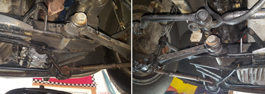
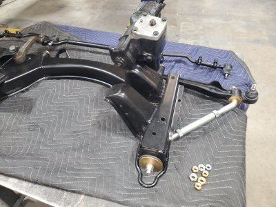
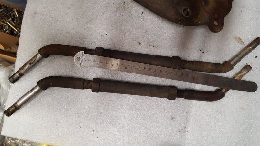
Also where did you get what appears to be an adjustible tension device to the wishbone? Could you post a closer photo if you have one and where you got it?

Thanks again
jjs2800cs
 
Yes, good question. I've not seen the adjustable aftermarket tension strut.
 
I wish I could provide more insight on those but they came with the car when I bought it. I just cleaned them up (zinc plated) and reused. I haven't actually even finished the alignment on my car so I can't say how helpful they are but they fit fine and do the job.
 

Attachments

  • asPurchased.png
    asPurchased.png
    785.8 KB · Views: 160
  • 20200307_150336.jpg
    20200307_150336.jpg
    374.4 KB · Views: 138
  • 20200307_150339.jpg
    20200307_150339.jpg
    390 KB · Views: 140
  • 20190126_163123.jpg
    20190126_163123.jpg
    338.1 KB · Views: 145
I have done it a couple of times with all the accessories, belts, fan, exhaust manifolds & downpipes already mounted. I would put the radiator in after the engine is in place.
 

Attachments

  • IMG_6496.jpeg
    IMG_6496.jpeg
    234.1 KB · Views: 136
  • IMG_6495.jpeg
    IMG_6495.jpeg
    249.6 KB · Views: 131
  • IMG_0876.jpeg
    IMG_0876.jpeg
    256.1 KB · Views: 145
I wish I could provide more insight on those but they came with the car when I bought it. I just cleaned them up (zinc plated) and reused. I haven't actually even finished the alignment on my car so I can't say how helpful they are but they fit fine and do the job.
I would think any adjustment there would stress the bushing.
 
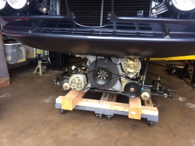
I installed my m90 with everything installed except for the headers. I used two furniture dollies joined together by 2x4s. I would shim the front a little to get the angle you need for the subframe to align with the frame rails. I used a low slung floorjack to achieve the final angle.
 

Attachments

  • 5D07E89B-7B65-42F5-A896-9738F63FE2A0.jpeg
    5D07E89B-7B65-42F5-A896-9738F63FE2A0.jpeg
    239.1 KB · Views: 130
  • 411C751B-B17B-4224-B0CD-2D4C1BABFC3A.jpeg
    411C751B-B17B-4224-B0CD-2D4C1BABFC3A.jpeg
    255.9 KB · Views: 131
  • 09260A9B-84F5-4DA4-95E4-90552DF5D429.jpeg
    09260A9B-84F5-4DA4-95E4-90552DF5D429.jpeg
    288.6 KB · Views: 130
  • B67614C9-5603-4DF1-A2C2-551B41764051.jpeg
    B67614C9-5603-4DF1-A2C2-551B41764051.jpeg
    310.1 KB · Views: 127
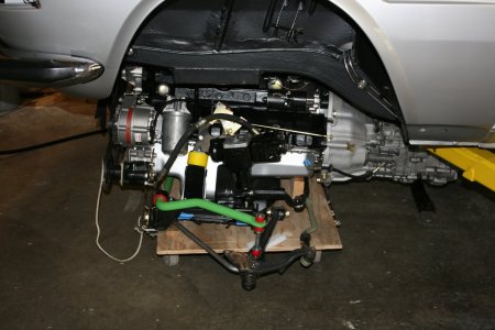
Here is how ours came out

1676683110826.png


1676683235383.png


We have a tranny jack under the tranny and a custom built wooden frame under the font carrier.

jjs2800cs
 
Just goes to show there are several ways to install the engine or pull it. I’m just pulling mine out followed by reinstalling it in a couple of months. Here’s what I did.
1. Pull off the intake (FI) with the ECU wiring harness.
2. Remove items that won’t clear the frame rails like the L bracket to the turbo.
3. Pull the radiator and hoses.
4. Remove the suspension and steering connectors, I’m leaving brakes and shock towers intact.
5. Disco PS pump from mounting bracket.
6. Remove 3 bolts from steering box to subframe.
7. Remove all mechanical and plumbing connections.
8. Make sure everything is clear of the body like tranny support. Driveline is out too.
9. Place dolly with 4’ of dunnage under engine tranny and lower Coupe so weight is slightly off subframe. Remove 4 bolts.
10. Slowly lift Coupe to clear combo.
Obviously you need a lift to do this and this is my 3rd time doing this with refinement each time. I’ll. Be doing this in 5-7 days.
Regards, Jon
 
Thanks for all the replies thus far. We are about a month or so away from installing the engine/tranny. Whole effort was pushed back due to having to have the shell repainted a second time. Long story.

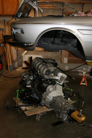
We had to get innovated in using our 4 post lift on how do you support the chassis at the front to allow the entire drive train to be removed.
It was a little scary but it worked very well. The two cantilevered supports actually have pins thru the wood going thru drain holes in the frame rails. Yes it does look scary.

So we have guidance now as to what we can install before going back in.

jjs2800cs

100_4887.JPG
100_4888.JPG
100_4915.JPG
 
Back
Top