73E9er
Member
With more rainy days coming here in Portland, OR, with the coupe idle in the garage, I set about tackling the installation of a relay in my low beam lights circuit - a project I'd meant to do years ago. I prepped the car, gaining access to the lights, removing the battery, etc. I had a hard copy of the Daniel Stern Lighting article on the subject, and my wiring diagram for the coupe.
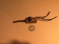
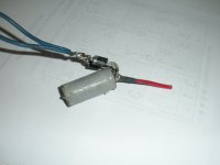
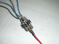
I thought I'd dismount the two existing relays (high beam, horn) from the mount next to the battery to give more access to the up-coming wiring effort. Upon pulling out the horn relay, I noticed that instead of two green/yellow leads coming from relay post 87, there was just a single red lead. What the...? I followed this lead a short distance to where it disappeared into an eight-inch length if electrical tape, at the other side of which, indeed, two green/yellow leads appeared. The wrapped length looked like a snake that swallowed a pig. I unwrapped the entire "thing" and found what is in the attached picture. There are four (4) resistors(?) labeled "DII/IN5401", and a 1-1/2" x 1/2" cylindrical element, labeled G(or Theda sign) 4/80XXXX (lettering rubbed off). What is this thing? Have I found my coupe's Flux Capacitor?
As my horns have always worked, even after my installing two FIAMMs a few years ago, I can only surmise that a previous owner/mechanic buggered this circuit to install a set of horns that had some unique electrical requirement - say, 6-volt horns. Looking back at my horn upgrade, I always thought that the FIAMMs should have been much louder!
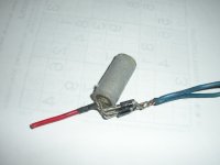
In any case, can anyone diagnose what this contraption is - and if I need worry about any downside from removing it and restoring my horn relay circuit to "stock"?
Thanks.
Gary
I thought I'd dismount the two existing relays (high beam, horn) from the mount next to the battery to give more access to the up-coming wiring effort. Upon pulling out the horn relay, I noticed that instead of two green/yellow leads coming from relay post 87, there was just a single red lead. What the...? I followed this lead a short distance to where it disappeared into an eight-inch length if electrical tape, at the other side of which, indeed, two green/yellow leads appeared. The wrapped length looked like a snake that swallowed a pig. I unwrapped the entire "thing" and found what is in the attached picture. There are four (4) resistors(?) labeled "DII/IN5401", and a 1-1/2" x 1/2" cylindrical element, labeled G(or Theda sign) 4/80XXXX (lettering rubbed off). What is this thing? Have I found my coupe's Flux Capacitor?
As my horns have always worked, even after my installing two FIAMMs a few years ago, I can only surmise that a previous owner/mechanic buggered this circuit to install a set of horns that had some unique electrical requirement - say, 6-volt horns. Looking back at my horn upgrade, I always thought that the FIAMMs should have been much louder!
In any case, can anyone diagnose what this contraption is - and if I need worry about any downside from removing it and restoring my horn relay circuit to "stock"?
Thanks.
Gary