Metric mechanic 4.0 l

Oldbmwcoupes

Well-Known Member
Messages
403
Reaction score
370
Location
Memphis, TN
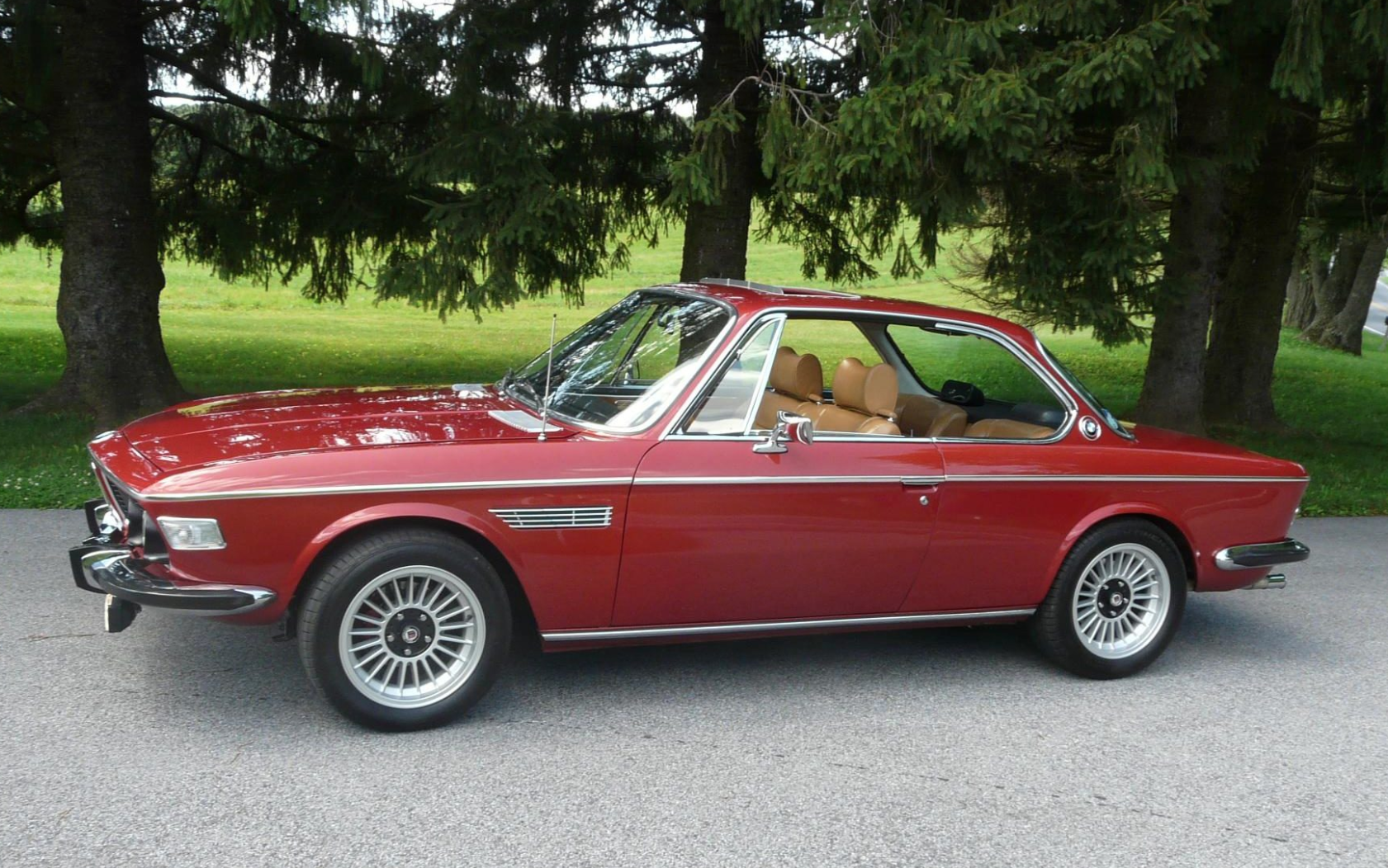
Like many members here, I’ve been collecting parts for my second “dream car”. It’s my 72 3.0 cs. It’s not nearly a nice car but it’s just bad enough for me to not worry about making it my perfect version of a coupe. I’ve recently picked up the engine through the car buddy network. It’s an interesting engine with some proprietary work. I thought many might find it interesting to see.

I plan on running an m90 intake with 320i plenums. Thinking it’s going to need moronic 1.3 to run properly. However it came complete with the b34 harness and brain etc. if anyone has specific experience I’d love to hear it. Thanks, Mark

431C23E4-A5B5-486B-94D9-274AB6437B2D.jpeg
F1986056-9705-4C62-86EC-91250E5B31B2.jpeg
B867377E-23FD-45B2-8038-1349F2BD4D28.jpeg
93809CC7-B51A-4E26-802C-8D1F8B9E9C7B.jpeg
3CD45F51-BDC6-4307-BBFD-7642F0C722F7.jpeg
 
@Gary Knox hd a 3.8L MM motor in his e9. Gary still lurks around here. Perhaps he can share some thoughts.

 
There's a few interesting things there:
1. ST valves aren't coked to heck, but I question their efficacy, especially on the combustion chamber side
2. Pistons are far less dished than I expected
3. I am surprised they didn't clear out the squish space to prevent detonation

Their big claim to fame is their rotating weight reduction, could you weigh pistons/rods so we can compare to a regular M30?

Can you measure the head ports and other head work?

Any chance we can get the head on a flow bench?

Lots of pictures, please!
 
Last edited:
I know there are lots of MM skeptics out there, but Gary liked his engine a lot.

I happen to have a set of those valves. x-atlas0 - why do you think they are not useful?
 
I know there are lots of MM skeptics out there, but Gary liked his engine a lot.

I happen to have a set of those valves. x-atlas0 - why do you think they are not useful?

The purpose of the surface turbulence (as I understand it) is to reduce the boundary layer thickness in a flow path, which increases the mass flow rate for a given cross section. This is why golf balls are dimpled. Inside the combustion chamber, those conditions aren't present, you aren't trying to move mass. Without moving mass, you don't get a boundary layer. If anything, I would think the grooves would promote wall wetting (the fuel dropping out of the intake mix and sticking to the combustion chamber walls) due to the creation of stagnant flow pockets. Wall wetting reduces the effective fuel combustion efficiency, reducing the power of the engine. That's part of why race engines sometimes have mirror-polished combustion chambers, it reduces the number of potential wall nucleation/deposition sites.

Basically, I'm saying the internal swirl flow boundary layer losses should be minimal during a cycle due to the swirl-driven boundary layer not significantly impacting swirl flow, as the majority of swirl motion (and therefore boundary layer impact) being instigated by the valves being open, so the flow isn't going over the combustion-side of the valve, it's going over the runner side.
 
Of course, combustion chamber modifications are mostly gilding the lily compared to head flow improvements with most BMW engines. To see what I mean, the S38 flows more base than the most aggressive M30 flow data I have seen, and it makes more power/torque than any M30 will in similar conditions, even with identical displacement.
 
I believe that part of Jim Rowe’s technique was to also the level of atomization within the combustion chamber- particularly during the later stages of compression. The better atomization allowed for higher compression ratios whole controlling pre-detonation. I’m not convinced that the s38 puts down that much more torque than a tuned m30. Some of the engines I’ve built (b34) have a harder pull though the first two gears (3.73) than my m5/m6 (3.91).

There are an infinite number of theories and arguments about this motor and it’s design. MM claimed 300 hp if I remember correctly. What I do like is that their success was based on empirical studies and lots of hands on cutting/testing/flowing over the years. The intake ports are considerably larger. I believe that the block is b35 or M90 (the only blocks I know of to be stamped with only 3.5 on it (doubt its s38). I’ll try to get some numbers for the sake of it and comparison.

I think the flat top had to be used to keep the compression from going sky high with the strokes crank (wondering if is s38b38 or 3.3li ?). I’ll probably give them a call and get more details to share. My recollection is that they used a different deep I-beam rod as well.

X atlas, I’ll try to get more comparisons in the next few days. I have an Alpina B10 head that I’ll compare it to as well (UK only, naturally aspirated b10, 260hp)
 
I believe that the block is b35 or M90 (the only blocks I know of to be stamped with only 3.5 on it (doubt its s38). I’ll try to get some numbers for the sake of it and comparison.

The m90 block and head have two steam vent holes between each cylinder. The B35 has one. I can’t tell if one side is gunked up on yours. Obviously the pistons aren’t original but the m90 also had flat pistons.

It’s also pretty easy to identify the m90 on the driver’s side if you post a full view. See post below.


3C9DEB01-ECB7-4AF5-945B-187B2B273B28.jpeg
C5858D27-6B7F-4952-AEBB-F48B47081781.jpeg
 
The B35 has an extra hole in the back:

F63C40D7-B4A7-49DF-BD84-9B84546AB5B9.jpeg


The B35 says 3.5 but doesn’t have the big water passage that goes to about cylinder #4
C26AA645-45A4-4B8D-B1C0-57F79D639BD6.jpeg


M90 3.5 with water passage.
F73E2E4B-E998-43A6-9D1D-FE7C2924FA46.jpeg


Lastly, you can always plug the VIN into realoem since the m90 and B35 are 17 digit VIN’s. M90’s start with “55”. If it is a 635 on a fringe date, navigate to the motor section and get the piston size. M90 is 93.4mm and a B35 is 92mm.
 
Last edited:
Interesting articles. Thanks for sharing. Most interesting to me was the mention in one article of a measurable drop in head temperature. This would seem to support the theory that this technique could allow for higher compression without the predetonation associated with heat.
 
@Markos, thanks for clarification. However, what’s really got me stumped is that the intake side casting is very simple and smooth compared to the detail on the b35. Also, there is no flywheel access hole. Yet it also doesn’t have the raised water passage on the intake side normally associated with the m90. I’ve attached a few photos. Perhaps someone more tech/info savvy than myself can figure out what block this really is- now it’s just a curiosity

0CB61558-E5E7-481B-B579-1C9FC7605CBC.jpeg
311DEB52-9976-4C85-8392-D1E57AF59947.jpeg
 
@Markos, thanks for clarification. However, what’s really got me stumped is that the intake side casting is very simple and smooth compared to the detail on the b35. Also, there is no flywheel access hole. Yet it also doesn’t have the raised water passage on the intake side normally associated with the m90. I’ve attached a few photos. Perhaps someone more tech/info savvy than myself can figure out what block this really is- now it’s just a curiosity

I verified that I misspoke. I searched the interweb and confirmed that BMW switched to an 8 digit code, which is visible on your starter boss. You can’t really tie that to the VIN from what I gather.

So since it doesn’t have the hole, and it’s 8 digits, and it says 3.5, it must be a B34. B34’s do say “3.5” on the block. It’s the intake manifold that doesn’t have the clear “3.5” labeling. IIRC, the B34 manifold looks quite similar to the “3.5” B35 manifold, but says “3.3/3.5”.

Lastly, I believe (but don’t quote me on it) that the late M90’s didn’t have that long water passage. Possibly the motronic M90’s.
 
I’ve had tremendous success porting my heads by hand. I’ve used an Alpina b10 head as my template. It’s not fancy but I enjoy doing it
 
The purpose of the surface turbulence (as I understand it) is to reduce the boundary layer thickness in a flow path, which increases the mass flow rate for a given cross section. This is why golf balls are dimpled. Inside the combustion chamber, those conditions aren't present, you aren't trying to move mass. Without moving mass, you don't get a boundary layer. If anything, I would think the grooves would promote wall wetting (the fuel dropping out of the intake mix and sticking to the combustion chamber walls) due to the creation of stagnant flow pockets. Wall wetting reduces the effective fuel combustion efficiency, reducing the power of the engine. That's part of why race engines sometimes have mirror-polished combustion chambers, it reduces the number of potential wall nucleation/deposition sites.

Basically, I'm saying the internal swirl flow boundary layer losses should be minimal during a cycle due to the swirl-driven boundary layer not significantly impacting swirl flow, as the majority of swirl motion (and therefore boundary layer impact) being instigated by the valves being open, so the flow isn't going over the combustion-side of the valve, it's going over the runner side.
I've never understood what MM was trying to do with those, which is why I picked up on your comment.

Your comment on surface turbulence and polishing actually fits better with my understanding of things. Last month I pulled the main and auxilliary venturies out of my carbs, removed what was left of the little casting fins, and cleaned up all the inner surfaces. They are not mirror polished, but they are now very smooth.
 
Back
Top