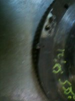
New flywheel is missing TDC trigger point!?

tomcolitt

(deceased)
Messages
289
Reaction score
4
Location
Los Angeles, CA
I just installed a new flywheel I picked up at a salvage yard because it was the lighter (16lbs vs. 21lbs) version, presumably from a later Motronic M30, which gets triggered at the front of the engine. I have the early Motronic with the two sensors in the bell housing. Does anyone have any experience with fitting this flywheel with the trigger piece off my old flywheel? It's held in place by a small roll pin and also I'd have to cut a notch or recess into the new flywheel for that trigger. I hope I can do that so it won't upset the balance of the flywheel too much.

Thanks, Tom
 
Custom Racing flywheels can have this, so I don't see why a machine shop couldn't make the provision for a trigger. Shouldn't be a big deal. I'd have them double check the surface too.
 
Sounds like you picked up a Jetronic flywheel which has no provision for any magnetic pickups.

All light flywheels were early sounds like you got a 533, 633, or 733 Jetronic flywheel, later flywheels became dual mass 25 lb monsters for civilized driving.

Only the m30 b35 used a front dampener pick up for engine management- earlier dampeners
had a pin only used for the diagnostic plug pickup.
 
Thanks guys. Well, then at least it sounds like I had no option of finding a lighter flywheel for an early motronic. Unfortunately, I already had the surface skimmed so now I'll figure out how to fit that trigger in there...Sometimes getting a part just because its cheap and seems right ends up being more hassle. (could've just lightened my original fw)
 
Thanks guys. Well, then at least it sounds like I had no option of finding a lighter flywheel for an early motronic. Unfortunately, I already had the surface skimmed so now I'll figure out how to fit that trigger in there...Sometimes getting a part just because its cheap and seems right ends up being more hassle. (could've just lightened my original fw)

Yeah, the early Motronic (since it was the only one to use the flywheel for crank position) used a unique flywheel. That said, since the crank position sensor is just a Hall effect sensor, the machine shop could tap a hole in the right place and fill it with a pin to emulate the original pickup. If you have your old flywheel out, they should be able to emulate it with a minimum of fuss. After all, it can't be too big, otherwise it would have unbalanced the flywheel.
 
Well, now I'm trying to figure out how the set-up works. I pulled out the old steel block that triggers the hall sensor and it is literally just a rectangular block that has a post attached to it which goes into a hole in the flywheel and is then retained by a rolled spring steel pin.

The block ends up only about 1mm taller than the rest of the flywheel circumference and you wonder that this was even enough to trigger the sensor. Also, the block is the whole width of the flywheel so I'm guessing they needed that width to trigger the hall sensor which is also about that same width. Just a pin might not be wide enough. Also, the flywheel has a little triangular shaped wedge cut out of it leading right up to the rectangular trigger block. I wonder if that is necessary in my new flywheel too? The hall sensor may need the larger "step-up" in steel material provided by the wedge and then the rectangular steel block. Does anyone know any of this for sure as I don't want to install the transmission and find that my sensor doesn't trigger anymore...
 
Tom,

Presumably, the sensor air gap is .7 to 1.3 mm on early motronic as it is for a front crank mounted one on later cars.
 
Hang on here.... That wedge cut out?? that is the trigger..

One sensor counts the 116 teeth [speed sensor]
One sensor counts a tab of metal on a pin for an automatic or a cutout for a manual[TDC]
 
Thanks Don

Don't know about an auto, but the manuals also have the 30mm wedge cutout followed by that metal tab that's retained by the 1mm spring pin... I'm guessing when the sensor "hits" that block/ tab, after the 300 mm void, it gets a feedback to the sensor because of this steel block moving through its magnetic field....(Hall effect). Yes?
 
Last edited:
I'm also slightly nervous that the new flywheel/ ring gear sits closer to the starter than the old one. I hope the starter won't interfere with the ring gear although I can't imagine they changed the starter mounting flange between the 3.3. and 3.5 blocks, or even the starter for that matter. I'm less worried that the transmission input shaft will not slide into the clutch quite as far as it did previously. There seems to be enough length on that splined input shaft.....
 
I think you should post a pic- I go to Double 02 often enough to take pics if you need.
 
Possibly adapt your pickup to use this http://www.02Again.com/?page_id=30 or fab your own using the engine dampener location.

Here's what I fabricated for a Hall sensor using the engine dampener.
P1010494.jpg


Doug
 
Last edited:
Pics of a Motronic flywheel for you.......
 

Attachments

  • flywheel1.jpg
    flywheel1.jpg
    71.1 KB · Views: 200
Hi Don

Thanks for the picture. That is exactly what I was trying to describe by the wedge followed by the trigger block. Don't you agree that BMW found that both the wedge AND the trigger Block were needed to reliably trigger the TDC sensor?

Today, I duplicated this exact same set-up on my new flywheel on a milling machine. But, since I didn't want to have to go back out and have the flywheel balanced, I thought I'd just cut a second wedge out of the flywheel at 180 degrees apart. While I was milling that one, I had a thought that made me stop right then. What if just the wedge alone is already enough to trigger the sensor (maybe not always and maybe not consistently, but maybe this is why BMW added the slightly taller trigger block after the wedge, so that the "step" that the hall sensor "sees" is big enough....). In that first case, I have just created a useless flywheel that is balanced but now has two TDC triggers for every revolution of the crank. Not good....
Does my thinking make sense to anyone? Does anybody know how this set-up/ sensor works for sure and has anybody modified the lighter flywheels for motronic 1.0 use?

I'm now trying to decide whether I need to fill in my second wedge cut-out again and get the flywheel balanced or whether the second which will definitely NOT, by itself, trigger the TDC sensor.

Thanks for the other suggestions too, but that really doesn't apply to my problem right now. If and when I experiment further with a motronic 1.3 set-up and sens I will just mount the stock trigger and sensor at the front of the engine....

Thanks for hanging in there with me and your ideas....
 
It looks like I'll have to find out the answer by trial and error. Since it's about $40 and a few days to balance my flywheel, I am now going ahead with my original plan instead, to machine an equal wedge at 180 degrees from TDC in order to have a fully balanced flywheel, but run the risk that this wedge (no trigger block though) will trigger the sensor two times per crankshaft revolution. In the worst case the engine won't run and I have to take the transmission out again...

Come to think of it. Has anyone ever installed just the bell housing with sensors and test run an engine that way? Seems like it should be okay, just for a few minutes in the shop? Thanks for the help. I'll come back once I have installed everything and let you know what I find. Maybe this thread will be helpful to someone who wants to do something similarly odd ball as I....
 
Just thought I'd let people know what the final verdict was on my lighter L-jet flywheel modified for Motronic 1.0 use. I went ahead and machined an identical (minus the trigger block) wedge/step on the other side (180 degrees) from the first one. I was worried I might get a second (false) TDC trigger per crank revolution. However, I went to start up and the engine ran fine. Even when I pulled the Hall sensor as far out of the bell housing as 10mm, the engine ran without problems, then quit, if I pulled it out just a little further. Obviously the Hall sensor is very easily "seeing" my trigger. I'm just surprised that it doesn't seem to see the "second" trigger wedge/step as well. I know that trigger block can't be made up of some magical trigger material. If it were, why not use just that block and forget about the wedges.

Anyway. I just thought someone might be interested. I have no out-of-balance issues, since the two wedges cancel each other, so after I figure out my starter issues (separate thread...), I'll do further testing to my 3.5 m30 B34/ B35/ Euro/ US/ upped the compression to 10 to 1 hybrid....
 
Back
Top