power for radio...what ign position?

teahead

aka "Rob"
Site Donor $
Messages
6,413
Reaction score
1,860
Location
Tacoma, WA, USA
Is the radio supposed to come on for the 1st turned position of the ignition switch?

or in the 2nd position (run position).

3rd position is crank of course.

Not getting power to the violet wire in either position.
 
1st position.

Strange, the purple wire should be the switched power...time to trace the circuit with an ammeter.
 
Silly question, but were you grounding your multimeter when you tested the violet wire?

I was just fiddling with the ignition wires two weeks
ago. I referenced a good image the blue book. If your violet wire really doesn’t have power, I would assume that you have a problem with your ignition switch.

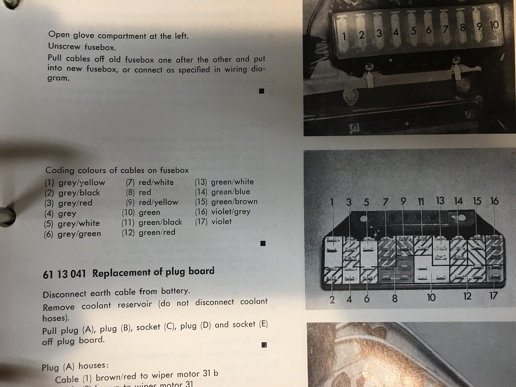
Blue book. The fuse block is upside down in the second pic.
26599570889_af7ab08f32_b.jpg
 
Clipboard01.jpg
ya, made sure the ground is definitely a ground.

Will have to check the ignition wire for sure. Looks bandaged up. Darn diagram I have, can't make out the color of the wire coming from the ign switch to fuse #10.
 
Last edited:
View attachment 33520 ya, made sure the ground is definitely a ground.

Will have to check the ignition wire for sure. Looks bandaged up. Darn diagram I have, can't make out the color of the wire coming from the ign switch to fuse #10.

Ignition switch to fuse 10 is the violet wire (on top) that you mentioned. I noticed this on my box recently and it coincides with the picture I posted above (pin 17) Also, you can ground anywhere on the body, no need to find a ground wire. I try to ground to a dedicated ground screw though. There are a few near the driver’s side kick panel up near the can relays.
 
Some pics of a spare fuse block that I picked up locally for $5. I can’t guarantee that everything is accurate but the violet is correct. Only one wire looks like a replacement. Make note of the orientation. The two mounting screws are on the bottom of the block.

Not from my CSI. With that one I pulled the entire wiring harness and connectors through the little hole in the firewall.

6C81EE44-5CDC-4AAC-96F4-A2DEF730DE03.jpeg
6D0C4DF8-DD89-40A2-ABDD-02B733B1D19F.jpeg
8C79B6B3-7FD6-4A5B-950C-7FD0647AB047.jpeg
 
If the ignition wire is "bandaged up" this is likely your problem. Check for continuity on this wire with the other end disconnected from the ignition switch.
 
Some pics of a spare fuse block that I picked up locally for $5.

View attachment 33533

This picture shows something important that is not illustrated well in the wiring diagrams. Note the jumpers in the fuse block where the incoming wires are attached across fuses 3 and 4; 5 and 6; and 7 and 8. You cannot isolate a circuit that runs through these fuses (chasing down a parasitic voltage drain, for example) without knowing that these connections exist.

EDIT: I appear to have the numbering in this post wrong because I counted from left to right looking at the back of the terminal. The correct numbering for the connected circuits is 4 to 5; 6 to 7 and 8 to 9. If you look at the picture of the wiring diagram posted above, you can see the connection between circuits 8 and 9 illustrated in the diagram.
 
Last edited:
I'm assuming incoming power is on the top; outgoing on the bottom spades?

Yup, and again pay attention to the orientation of the fuse block. To beat a dead horse, the two mounting tabs are on the bottom. Perhaps a wiring expert can explain why the incoming power would be doubled up on the incoming side.

I believe that the black line on the back of each spot represents the split between Incomming versus Outgoing terminals. You have room on most of the fuses to add fused power without “tapping” into an existing wire.

I'm no wiring expert, but I think of the "jumpers" as providing power distribution. Thus, not both top wires are "incoming." Some distribute switched power, some distribute power subject to the load shedding relay, etc.

And I agree that the black line is an insulator between incoming and outgoing current flows, forcing current to flow through the fuses. Note too that this is where the markings on the back of the fuse block change color. I've not added circuits using the additional tabs on the back of the fuse block, but this would be the most elegant way of adding new circuitry. (Perhaps doing this upside down with the door channel sticking into my ribs has dissuaded me.)
 
I’ll need to think a about all of this later. I have much to learn about wiring these cars. Fortunately, not many wires.
 
Back
Top