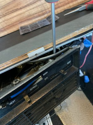
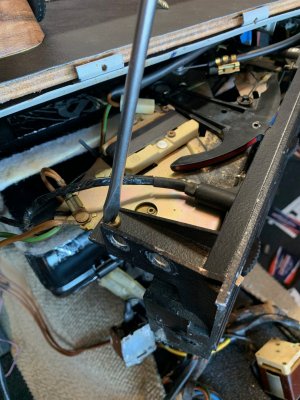
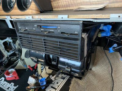
Part 1: Preparation:
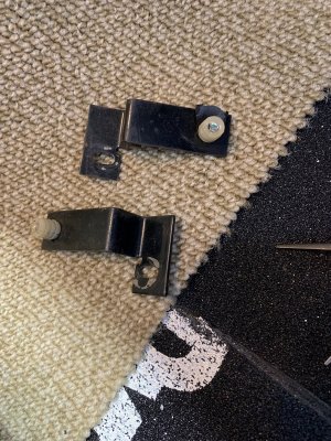
Here are the parts you will need:
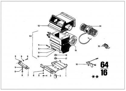
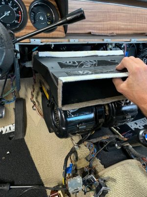
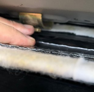
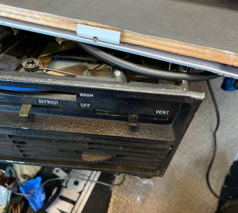
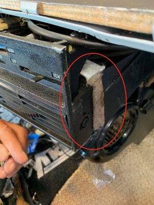
Throughly clean the air box and reinstall fresh felt around all of its leading edges to ensure good air sealing. I got rid of the foam pad which had deteriorated and did not seem to do that much anyway.
I later added a few strips of dynamat to tone down the vibrations
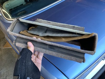
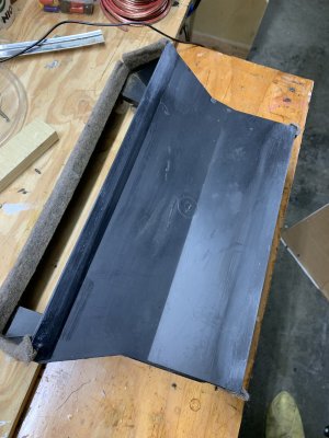
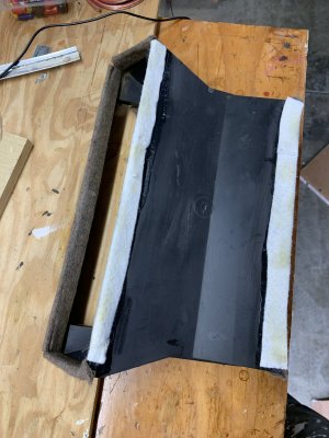
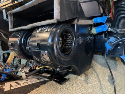
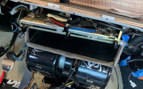
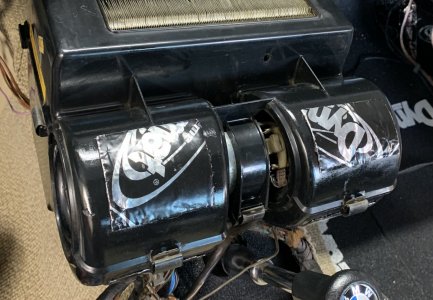
Disassemble the Evaporator to clean it up, removing all rotting foam and accumulated dust
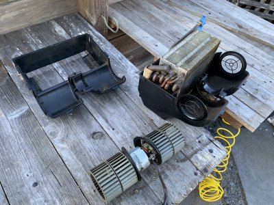
At this point I would highly recommend getting @Blinkling ‘s upgraded evaporator guts. It’s an affordable yet significant upgrade and it will never be easier to do than now.
After re-assembly, add some sort of vibration dampening on the rounded parts outside the squirrel cages to replace the ones that were there from the factory
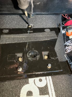
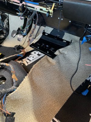
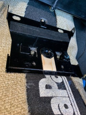
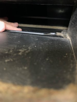
Throughly clean and rust proof the evaporator metal frame that sits on top of the tranny tunnel. Note that mine, as well as some others I have seen, had its front section removed by some audio terrorists (as member xxxx would say) in a past life. Fortunately that does not seem to cause problems.
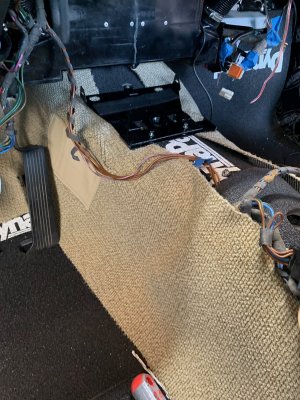
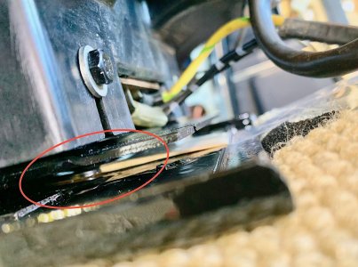
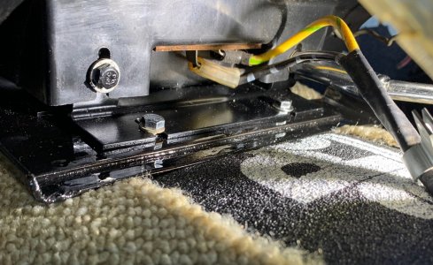
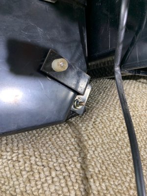
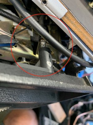
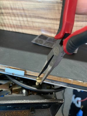
Do the same for the front L bracket which will anchor the front of the evaporator unit. (NOTE: The pic on the right below shows where this L Bracket will eventually reside after the evaporator is installed. But it should not be bolted there at this point. It should be secured to the front of the evaporator unit prior to sliding it into position. Loosely tighten it there)
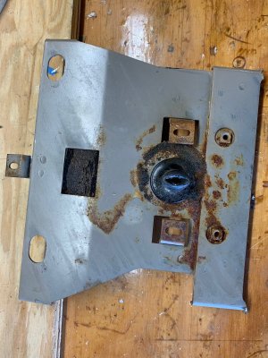
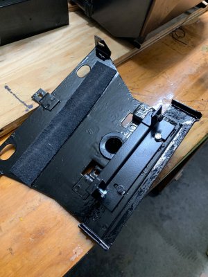
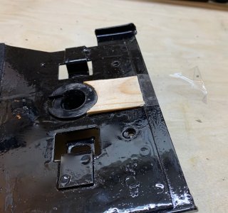
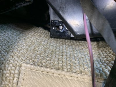
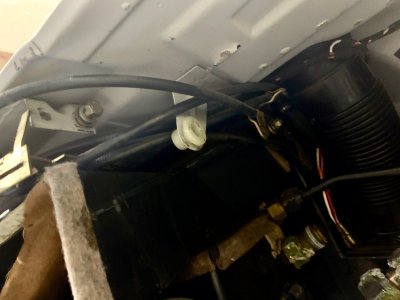
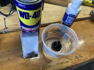
Pay special attention to the the rubber drain funnel (seen above) which must be cleaned and should be brought back to life with some rubber restorer. I also cleaned the original sheet screws with WD40 because they were in good shape and I did not have new ones on hand.
Install whatever sound and heat protection you plan to install on top of the tranny tunnel. In my case it was Dynamat first and Dynapad on top of that
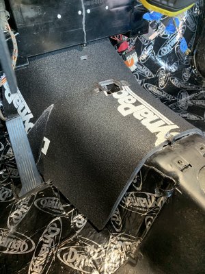
Clean up and secure all electrical wires that are above where the console will go
Now is the time to install speaker wires if you plan to use those. Note: Always run your speaker wires on the passenger side of the car. Things are already too cramped on the driver side
I decided to decided to cut a square “gasket” around the drain funnel out of a material that was heat and moisture resistant since this would go over the hole in the tranny tunnel. The first one I did was too thick so I had to slice its thickness in half
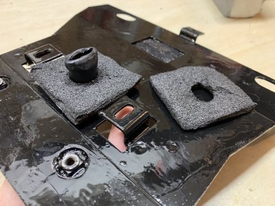
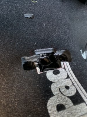
Cut holes in your insulation where the 3 (or 5 if yours still has the front section) bracket screws plus the square drain hole gasket will go. You want to lower those areas as much as possible because the fit will be very tight.
Here are the parts you will need:

Throughly clean the air box and reinstall fresh felt around all of its leading edges to ensure good air sealing. I got rid of the foam pad which had deteriorated and did not seem to do that much anyway.
I later added a few strips of dynamat to tone down the vibrations


Disassemble the Evaporator to clean it up, removing all rotting foam and accumulated dust

At this point I would highly recommend getting @Blinkling ‘s upgraded evaporator guts. It’s an affordable yet significant upgrade and it will never be easier to do than now.
After re-assembly, add some sort of vibration dampening on the rounded parts outside the squirrel cages to replace the ones that were there from the factory

Throughly clean and rust proof the evaporator metal frame that sits on top of the tranny tunnel. Note that mine, as well as some others I have seen, had its front section removed by some audio terrorists (as member xxxx would say) in a past life. Fortunately that does not seem to cause problems.
Do the same for the front L bracket which will anchor the front of the evaporator unit. (NOTE: The pic on the right below shows where this L Bracket will eventually reside after the evaporator is installed. But it should not be bolted there at this point. It should be secured to the front of the evaporator unit prior to sliding it into position. Loosely tighten it there)


Pay special attention to the the rubber drain funnel (seen above) which must be cleaned and should be brought back to life with some rubber restorer. I also cleaned the original sheet screws with WD40 because they were in good shape and I did not have new ones on hand.

Install whatever sound and heat protection you plan to install on top of the tranny tunnel. In my case it was Dynamat first and Dynapad on top of that

Clean up and secure all electrical wires that are above where the console will go
Now is the time to install speaker wires if you plan to use those. Note: Always run your speaker wires on the passenger side of the car. Things are already too cramped on the driver side
I decided to decided to cut a square “gasket” around the drain funnel out of a material that was heat and moisture resistant since this would go over the hole in the tranny tunnel. The first one I did was too thick so I had to slice its thickness in half

Cut holes in your insulation where the 3 (or 5 if yours still has the front section) bracket screws plus the square drain hole gasket will go. You want to lower those areas as much as possible because the fit will be very tight.

Last edited:


