Sunroof howto wanted

aearch

Well-Known Member
Site Donor $
Messages
4,116
Reaction score
589
Location
pleasant hill , ca
TEP GOOD WRITE-UP
IM HAVE AN ISSUE ALSO AS THE SUNROOF STOPS RIGHT AS IT GET TO THE TABS TO RAISE IT
IT STOPS DEAD AND WONT GO FURTHUR, SO I NEED TO CHECK ALL THE UNITS
TO SEE WHATS HOLDING IT
ILL KEEP UP ON THE PROGRESS
 

pickman

Well-Known Member
Site Donor $
Messages
406
Reaction score
132
Location
South Haven Michigan
You can remove the sunroof headliner by removing the two curved polished aluminum tracks and slide it straight out or in without removing the entire track system.

Good write up !
 

jefflit

Well-Known Member
Site Donor $
Messages
328
Reaction score
508
Location
Los Angeles, CA
Yes, the lizard is gone. A little more detail on those alignment pins for the record:

They come in two versions, a single-prong for the electric operation and a dual "tuning fork" version for the manual.

On a manual operated sunroof, the cables and cranking point are all up front, leaving both circular tracks in the aluminum open at the rear end. Thus, they can use the dual pronged approach to securing the rear. But in an electric roof the cranking point (the motor/gearbox) and cables are in the back so one of the circular tracks on each side has a cable in it so one track is available to hold the alignment pin.

In an example of poor design, Golde put the fat end of these alignment pins in different locations, thus requiring different hole locations in the rear sunroof frame for electric versus manual roofs. If they had put the fat pin on one side of the manual fork instead of in the middle then they wouldn't have had to have unique frames. Whatever. The result, however, is a slight complication for someone converting from manual to electric. You must either cut off one pin from the forks so you can still insert it in the free track or just give up on having rear alignment altogether. But you can't use the electric alignment pin, as your car won't have the hole int he proper location for it to locate into. The truth is, the alignment pins are way more important in a manual sunroof car than in an electric because with the electric version the rails are already securely located by the cables.
 

Attachments

  • manualRoofAlignmentPin.png
    manualRoofAlignmentPin.png
    273.3 KB · Views: 80
  • electricRoofAlignmentPin.png
    electricRoofAlignmentPin.png
    336.8 KB · Views: 80

jefflit

Well-Known Member
Site Donor $
Messages
328
Reaction score
508
Location
Los Angeles, CA
The (hopefully) definitive word on sunroof operation and alignment. Combine with early posts in this thread on removal, install, and motor/drive.

A few people have posted about problems with their sunroofs not popping up in the back and I recently encountered the same thing putting the Polaris CSE back together so I thought I'd write up my findings. This is all for an electric version. Manual is identical in most respects.

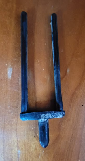
The roof panel is held in place by two guide brackets in front that have a plastic-covered u-shaped slot that rides along the lower inner edge of the side rails.
The panel is further attached to the car by the brackets on the cables.

attachmentPoints.png


The gear on the motor (or crank) engages the ridges on both cables, pushing or pulling them in two different directions
gearEngagement.png


When closing, the cables are pushed (pulled in a manual version) forward until they get close to the bump stops built into the car which protrude in the middle of the side rails. The first part of the sunroof assembly to encounter these bump stops are two little plastic wedges attached to the sunroof panel. These wedges hit the bump stop and slide upwards over the top of them, lifting the panel upwards. The front can't lift up, as the u-shaped glides keep it vertically fixed. But the rear can lift because the brackets on the cables are attached via hinges that can swivel upwards. Without these wedges the hinges will just ram up against the bump stops and jam, not lifting. See video. The wedges slip over tabs in the panel. If you need wedges, I have a CAD Step file so you can 3D print replacements. Just pm me.

wedge.png
wedgeLocation.png


The hinges on the cables ride up the bump stop, lifting the back of the panel until the panel is fully closed.

There are two rollers attached to pins sticking out of the cable brackets. These rollers fit along (above) spring steel tracks attached to the panel. (Normally they are black, I had to turn some new ones out of Delrin so the ones in the photo below are white.). Most of the time, the relationship of the roller to the panel is fixed (the brackets are bolted to the panel) but when the panel lifts at the hinges, this changes the distance between the cable (and pin/roller) and the bracket/panel. When lifted up there is pressure exerted on the metal springs against the rollers. When opening, the spring tracks pull the back of the panel down, allowing it to slip back below the roof.

rollerAndSpring.png


So, if you are missing the plastic wedges, the panel may not close all the way and may not lift up. If you are missing the plastic rollers (or if the spring is incorrectly installed above the rollers), your panel may not drop properly in the back when opening. Note that if you just have the pin and not the roller it might work ok but you'll get a better drop with the roller as it increases the spring tension a tad. If you don't have the pins at all then it really has nothing to help it drop.

@Markos already posted a good video showing this in operation. Note that he has the pins but not the rollers. I think this was how the cables came originally so maybe the rollers are overkill.


Assuming all the parts are there, let's take a look at adjustment...

The adjustment points are:
  1. The cables can be pulled/pushed to adjust their length, based on where they engage with the motor (or crank) gear
  2. Front guide brackets are slotted for side to side adjustment
  3. Front guide bracket mounting points have threaded knurled barrels for front height and guide angle adjustment
  4. Cable mounting brackets have elongated holes, allowing for fine adjustment side to side and a bit fore/aft
  5. Cable hinges have serrated teeth and a screw for adjusting rear height

Start by adjusting the cable length to get them as even as possible. Remove the motor drive (or crank) and pull the cables until both are just touching the bump stops then install the gear. They may not be exactly the same but the small difference can be compensated for with cable brackets and the hinge height adjustment later.

Next, install the front guides. Turn the knurled adjustment barrels to a good guessing point but be sure to look at the angle of the bracket. Keep the height of the two barrels even enough that the guide engages evenly with the rails, not binding. Adjust the guides in their slots so that they securely hold the panel in place but don't rub too much against the rails. Place the metal clip on over the slot before inserting the screws so that the screws have a clean surface to tighten against. If you don't have the clips, use washers.

1659984109477.png


Swivel the metal springs out of the way and begin securing the cable brackets to the panel. You'll notice the elongated holes allow some adjustment. Most of the adjustment is side-to-side but there is a small amount of fore/aft tolerance also (in case you couldn't get the lengths exactly even earlier). Make sure the panel is square in the roof and attach each cable so that they naturally meet the panel. Use the metal plates between the brackets and the bolts. They slide under the metal tabs on the panel. If you don't have the plates, use washers. When done, swivel the metal spring back into place below the roller (or pin).

bracketHoles.png
rollerAndSpring.png


Now it is time to test. Adjust the front height when closed using the barrels. Adjust the rear height by sticking a screwdriver in between the panel and rails to loosen the toothed hinge adjuster. Lift or lower as required and tighten back up again. The photo below shows the adjustment teeth and how the hinges ride up over the bump stop.

hingeHeightAdjust.png


That's about all there is to it. I found that improperly installed velvet weatherstrip "rope" can interfere. This guy does a decent job explaining how to install new seals at:
but you might need to tweak things a bit. I had to trim where the body seals turn down and enter the rear cavity. Also, this panel wasn't lifting at first, despite having everything in place. This was due to the corners being too tight for the panel to move all the way forward. We had to massage the velvet seal a bit to get it all working properly.

 
Last edited:

Barry.b

Well-Known Member
Messages
626
Reaction score
439
Location
Ireland
Hi guys
For the electric sunroof all of what you posted is excellent advice !!
What I would also like to highlight is once everything is aligned and cleaned and running smoothly, your drive motor might still not have enough drive to actually close the sunroof properly.
There are no limit switches anywhere to tell the motor “stop running “. It instead relies on a type of drive clutch.
That clutch is set up at the factory to slip before any cables or teeth get stripped from the drive mechanism.
But 50 years on the clutch is probably worn , so she slips before it should, thus the sunroof will not pop up in the rear.
I fixed my slipping clutch , so now she pops up again.
I have attached the method I used below. It might be a help to others.
 

jefflit

Well-Known Member
Site Donor $
Messages
328
Reaction score
508
Location
Los Angeles, CA
Trying to keep all sunroof stuff in one thread. Recent question on weatherstrip. Referring to diagram at https://www.wallothnesch.com/en/roof/bmw-2-5-cs-3-0-csl-e9/catalog-picture-54-01.html , you need:
If you don't already have a freshly painted sunroof panel (you did remember to paint the underside, right? Especially along the front 2 inches or so because it is visible from the interior when open.) then remove your panel and place it on a bench.

Reminder: the easiest way to remove panel is to open part way, remove the two aluminum corner trim pieces from the front corners (4 screws, 2 per side) of the opening, also remove or loosen the screws on the side aluminum tracks so they can be lifted at the front, pull down on the front edge of the headliner trim on the panel (there are 4 clips), then slide the trim panel forward and out along the tracks towards the front. Now you have access to the 4 (2 per side) 8mm bolts attaching the cable brackets to the panel, as well as the 4 Phillips head screws attaching the front guides to the panel. Then you can pull the panel out the front.

Protect paint with blue painter's tape as appropriate.

With the panel on the bench, make note of how far the velvet trim on rear edge extends and how it is tapered at the ends. You're going to need to mimic this. Then you can remove the velvet.

Then remove the cracked rubber along the rear shelf on the panel and clean it up for paint/glue. Paint now if necessary.

Using a good contact cement for rubber, such as Wurth, cut the rubber from to length and glue down in same orientation and position as original.
oldRearSeal.jpg
cleanedForRubber.jpg
rearSeal.jpg
rearRubber.jpg


Trim one end of velvet (the sunroof velvet is not as stiff as the roof velvet as it doesn't have the same metal inside), at an angle matching original and begin glueing to rear of panel. Trim other end to match when you get there.

See video above for glueing velvet to roof. I found I needed to trim the ends a bit and really stuff them into the sides.
installed.jpg


While we're discussing trim, we might as well talk headliner.... I'm not going to get into the minutia of colors and patterns and thicknesses of available materials. I think all non-CSL cars had white/off-white and CSLs could (or all?) had black. This is covered in detail in another thread.

headliner.jpg


The sunroof cars don't have traditional headliner bows. Instead the fabric is glued to a (cardboard?) panel behind the opening. This panel is covered with a thin foam on the underside and plastic to protect from water on the top side and is often toast. I pity you if you have nothing to work from but if you can tape and cobble your old one together then you can use it as a mold for a fiberglass reproduction as I did. It is held to the roof by 5 clips and gets tucked under the rear glass/roof edge. The corners are held up by the grab handles.

originalBacking.jpg


backingPanelCorner.jpg


reproBacking.jpg


The front visor panel is different on manual and electric models, as the crank or switch area differs. The corners of this piece are usually roached. Be sure that your rearview mirror bracket base is attached to the roof before installing this panel. Once this is held in by the front glass rubber, visors, side rubber and trim, etc. it is virtually impossible to remove.

visorPanels.jpg


I hired some guys to actually install my headline so I will leave the details of that to someone else....
 

Honest989

New Member
Messages
3
Reaction score
0
Location
Kingston upon Thames
Hey all.

Probably an old thread by now but I have two questions:

#1 What are the dimensions of the sliding sunroof panel on these cars
Or
#2 what's the length of seal you get for both rear and front seals? (The velvet ones)

The reason I ask is... Volvo 240s had this exact sunroof. The aftermarket seals that Volvo sells are terrible and not at all like the originals. After some research, I found that Porsche 911s had this roof and their aftermarket seals were a match but too short. I'm hoping BMW had a similar dimension of sunroof! (93 X 50 cm's )
 

Ian C

Well-Known Member
Site Donor
Messages
214
Reaction score
112
Location
Kyneton Australia
The panel is roughly 39.5 x 89.5 cm, long seal about 1540-50mm. , short seal maybe 950mm. Hard to measure accurately while installed.
 

eriknetherlands

Moderator
Site Donor
Messages
2,773
Reaction score
2,007
Location
Netherlands, Eindhoven area
@jefflit; just reading up on this thread, (thanks to the lizard ;-) ).

Great work with all the pics and explanations. You have quite some attention to detail.
I bet others with sunroofs will benefit from it.

Might be a good thing to move this to the DIY section as a knowledge base - let me know if that's OK with you.
 

Honest989

New Member
Messages
3
Reaction score
0
Location
Kingston upon Thames
Actually I have one last question. Having put it all back together, and wound it all up, I find that I have about the thickness of a 2pence between the rear seal and back of the hole for the sun roof. The cables are aligned, the panel is square... What is going on here? It's almost as if it winds too far forward
1000018895.jpg
 

jefflit

Well-Known Member
Site Donor $
Messages
328
Reaction score
508
Location
Los Angeles, CA
That's odd. What does it look like in front? If the front has the velvet seal all along the front edge and corners and there is an even gap (width of velvet rope seal) between the front edge of hole and panel then ??? Either the hole is too big or panel is too small. Neither seems likely but these are old cars....

If the gap up front is too tight for some reason, then the movement of the panel is limited by the seal (the front seal has a fairly solid cording rope material inside -- I assume you didn't use the more squishy rear velvet seal material up front, as it does not have the internal cording) and where the cable mech hits the round posts in the rails. You can see in the photo below that the holes on the attached bracket are oval, allowing for some for/aft adjustment of the panel to the cable, and thus within the hole in the roof.
The gap should be close to even all the way around. That said, a small gap between the rear velvet and the rear edge of the hole isn't the end of the world. The entire thing is assumed to leak. Water entering the rear falls onto the shelf at the rear of the panel, which has (or should have) a rubber seal that prevents it from dripping backwards onto the headliner. Instead, it is directed to the side rails, where there are drains in the front and rear corners.

1712098566250.png
 

bavbob

Well-Known Member
Site Donor
Messages
3,373
Reaction score
1,587
Location
Boston, Ma
Has anybody found a good substitute for the seals which seem to increase in price every day?
 
Top