Thermo fan question

Deesta

Active Member
Messages
59
Reaction score
2
Location
Brisbane
Good evening all

Well I replaced the fan with two x 10" thermo fans and updated my thermostat housing and thermostat so that I could house a thermo fan switch. I installed a standard relay and a TFS106 (a thermo fan switch which comes on at 95 degrees celcius and goes off at 90 degrees). The default is open. Anyway I cant get the fans to cut in. I tried another TFS106 and I go the same result. I tried another relay housing and relay and still no success.

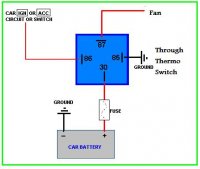
The fans come in when I connect them directly to the battery. I have wired the relay as per the following diagram and I have also tried a couple of other combinations, however I still can't get them to kick in. Any ideas?
 

Attachments

  • thermofanwire.jpg
    thermofanwire.jpg
    17.3 KB · Views: 124
Do your fans run if you jumper the switch? Do you have 12v on 86 and 30 when the key is on? If you ground 85 directly do the fans run? Do you have 12v on 87 when the relay is energized?
 
I’ll chime in with Mr. Goble’s thoughts...
He has the five tests right!
 
Do your fans run if you jumper the switch? Do you have 12v on 86 and 30 when the key is on? If you ground 85 directly do the fans run? Do you have 12v on 87 when the relay is energized?
Mike, you are good!! Not sure what you mean by jumper the switch, it have two prongs, an earth and a wire from the relay. I have grounded 85 directly with no result. I will check if I have 12v on 86 and 30 when I get home. Thanks for your advice.
 
In order to jumper the switch, use a short length of wire to connect the two terminals on the switch. This allows the voltage from the switched power to "jump" around the switch to ground and should cause the fans to run if the rest of the circuit is correct.
 
Do your fans run if you jumper the switch? Do you have 12v on 86 and 30 when the key is on? If you ground 85 directly do the fans run? Do you have 12v on 87 when the relay is energized?
Mike, I jumpered the TFS, no luck (fans not engaging), however I get a reading of 0.68 ohms on the wire leading to the TFS and of course at the TFS BUT regardless of if I jumper it or not.
I get 0.01 @ 86 with the key on
I get 0.L @ 87
I get a reading of 0.03 directly from the fan wire (so fan not connected to anything).

Now I'm lost!

You need 12v on 30. If it isn't there, check the connections to the fuse and hot wire ( battery, etc ).
You need 12v on 86 when the key is on. If it isn't there, you can jump 30 to 86 to test the rest of the circuit.
If you have 12v on both 30 and 86 and ground 85 the relay should energize. You will hear an audible click.
When the relay energizes, you should have 12v on 87 and the fans should run.
A test lamp is the easiest way to troubleshoot this circuit, if you poke the connection and the lamp doesn't light you don't have 12v.
$4 at Harbor Freight:

image_17623.jpg
 
I'll add one bit of trouble shooting wisdom to this excellent thread. I had a tail light that wouldn't light and a new bulb didn't resolve the issue. I measured 12 volts at the pins on the socket with a volt meter but still no joy. What I found was that the fuse had corroded and was passing just enough voltage to register, but as soon as any drain was put on it by the bulb, the resistance of the fuse wouldn't let any amperage through and the voltage would fall to zero. Cleaning the fuse restored things to proper operation.
So the simple bulb tester shown above would have been helpful to chase my issue down. Just remember you need both volts and amps to make things happen.

Ian
 
Could you please detail how you conducted the test of the wire leading to the TFS? If you get a reading of 0.68 ohms placing the probe at terminal 85 with the other end at the same wire connected to TFS, this reading is way too high. If you are probing the connection between terminal 85 and the other side of the TFS, this reading is too low. Also, either of these readings should change when you jumper the switch.
 
Could you please detail how you conducted the test of the wire leading to the TFS? If you get a reading of 0.68 ohms placing the probe at terminal 85 with the other end at the same wire connected to TFS, this reading is way too high. If you are probing the connection between terminal 85 and the other side of the TFS, this reading is too low. Also, either of these readings should change when you jumper the switch.

While more than it should be, in reality the 0.68 ohms of the wire will have no effect when placed in series with 80 ohms (roughly) of the relay coil. It takes about 150 milliamps to energize the relay.
In the same vein, to add a little info to Ian's post about the corroded fuse connections. When you use a modern digital volt meter with a very high input impedance to measure voltage, the resistance of a corroded connection pales in comparison to the many megohms of the meter circuit, and you will read source voltage at any point in the circuit. If you use a test light, the resistance of the bulb is now less than that of the corroded connection and the voltage drop across the fuse will be significant.
 
Last edited:
While more than it should be, in reality the 0.68 ohms of the wire will have no effect when placed in series with 80 ohms (roughly) of the relay coil. It takes about 150 milliamps to energize the relay.
In the same vein, to add a little info to Ian's post about the corroded fuse connections, when you use a modern digital volt meter with a very high input impedance to measure voltage, the resistance of a corroded connection pales in comparison to the many megohms of the meter circuit, and you will read source voltage at any point in the circuit. If you use a test light, the resistance of the bulb is now less than that of the corroded connection and the voltage drop across the fuse will be significant.

Mike makes a point; given that the entire circuit is not working fixing small problems like the high resistance in this wire is not the top priority. Nonetheless, when I was trouble shooting my electrical system I chose to address problems like the one indicated by this reading. And if I found something like this on a new circuit I had just installed, I would conclude I made a mistake and would double check my work.

Deesta -- please test for voltage on the same terminals you tested yesterday, both with the ignition on and with the ignition off.
 
You need 12v on 30. If it isn't there, check the connections to the fuse and hot wire ( battery, etc ).
You need 12v on 86 when the key is on. If it isn't there, you can jump 30 to 86 to test the rest of the circuit.
If you have 12v on both 30 and 86 and ground 85 the relay should energize. You will hear an audible click.
When the relay energizes, you should have 12v on 87 and the fans should run.
A test lamp is the easiest way to troubleshoot this circuit, if you poke the connection and the lamp doesn't light you don't have 12v.
$4 at Harbor Freight:

image_17623.jpg
Mike, you were spot on. I actually had a test lamp so I put it straight to use. I followed your instructions and discovered that I had wired 86 via the horn relay however on the wrong side (rookie error). So I rerouted the wire and woolah!!!! It worked. Thanks so much for the advice. I would never had figured that one out! Also thanks to others for your advice. Great forum.
 
Back
Top