Weak spots of the body, Tunnel, is it one of them?

eriknetherlands

Moderator
Site Donor
Messages
3,044
Reaction score
2,287
Location
Netherlands, Eindhoven area
Guys,

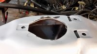
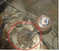
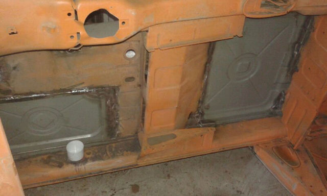
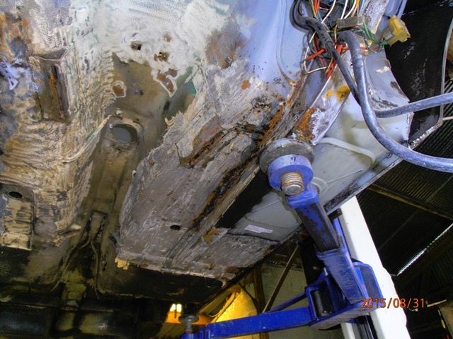
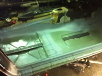
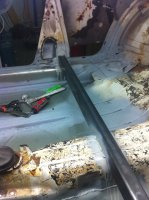
in the process of working on my floors, i cleaned the bottom and top side of the tunnel, just in front of the shifter console. Automatic in my case, it is mounted with 3 screws using speednuts on the body.

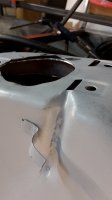
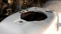
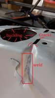
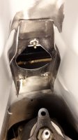
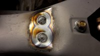
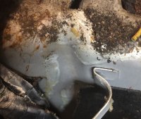
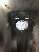
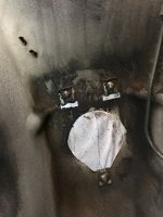
I noticed that the large semi round opening is all warped with random 'hills' and 'valleys', and 3 hairline cracks are coming out of one of the holes for the speednuts. See pics.
The deformations are strange because the matching surface of the shifter console (automatic in my case) is fully flat. Thus i expect the body to be flat, or at least symetric.
I doubt the cracks have to do with me removing the sills on one side, as cracks grow over time. Bending or buckling a car just gives you folds, not cracks.

Even more strange is a weld that is located in the groove for the wiring harness that runs down the right side of the tunnel to the floor. The weld is very factory looking, as it had the original interior paint, glue and isolation still stuck on top of it. But this weld does not connect metal structures, it can only be laid down as a repair. Were the factory pressings already showing tears during production? That would be strange...

What is going on here? is this area prone to buckling? Does it flex due to the transission casing being mounted roughly 30cm / 1 foot below it?

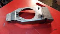
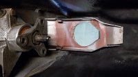
Attached also a pic of a reinforcement that I made up , which I am currently debating to weld to the body from the underside. (which is a nice insight into my mind; first make it then ponder wether it would be a good thing to do...)

question 2. Is this area the same for stick shifts; hole position, 3D curvatue / shape? In other words, If i weld my reinforcement into the body, am I then creating an obstruction for a future Auto to Manual conversion?

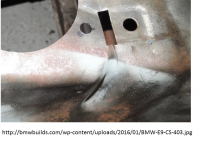
Picture "webimage" shows a pic that i just found with google. Here by coincedence the same type of cracks can be seen .

Erik.
 

Attachments

  • 20170107_171725.jpg
    20170107_171725.jpg
    331.8 KB · Views: 212
  • 20170107_171735.jpg
    20170107_171735.jpg
    160 KB · Views: 198
  • 20170107_171748.jpg
    20170107_171748.jpg
    364.7 KB · Views: 196
  • 20170110_064058.jpg
    20170110_064058.jpg
    375.8 KB · Views: 203
  • 20170107_171649.jpg
    20170107_171649.jpg
    399.5 KB · Views: 200
  • 20170107_171735-01.jpg
    20170107_171735-01.jpg
    175.4 KB · Views: 194
  • webimage.png
    webimage.png
    418.3 KB · Views: 192
Last edited:
i think the shift location is constant
bmw would not make two different location for the
manual / auto option.
and people change them out all the time
 
question 2. Is this area the same for stick shifts; hole position, 3D curvatue / shape? In other words, If i weld my reinforcement into the body, am I then creating an obstruction for a future Auto to Manual conversion?


The 4 speed shift platform is real tight up against the tunnel. I just installed a new foam piece that goes between, and it's practically being squeezed out of the shifter hole. There's some chance your reinforcement will interfere with that shift platform, but it's not likely you'd use an original 4 speed if you converted. Probably a 5 speed, possibly with the aluminum bar style shifter platform, which would be less likely to interfere.
 
BMW should have rounded the openings to prevent the cracking sort of like the D'Havalland Comet with it's square windows.

Weld the cracks and then round the corners to prevent future cracking.

Most of our cars have seen some sort of accident which may cause the wrinkling or deformation. Hard undulations from throttle and off throttle driving can cause the tunnel to compress.
 
to update and close.
As per advise I've welded up the cracks after drilling a small hole at the end of the crack.
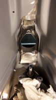
Then I decided it is necessary not only fix what was broken, but also to strengthen it so it doesn't break again. Thus I fitted the reinforcement; It's welded in now, no going back anymore!

(Pic is looking up into the tunnel from below the car)
 

Attachments

  • 20170117_221300.jpg
    20170117_221300.jpg
    186.2 KB · Views: 158
Just noticed that also new member NONO88's car also has some deformation in this area.


(Not judging if it's bad or not, just identifying that it seems to be a common thing and not just happening on my E9 alone )
His car is a stick shift, mine is automatic.
 

Attachments

  • Car from member NONO88.png
    Car from member NONO88.png
    420.4 KB · Views: 173
they all have this strain to avoid a water back.
but as they were made hand it is never the same...
 
Yes this is to avoid that the water coming in the cockpit.

Sometimes you have 1 deformation, sometimes 2, It dépends of the date of construction
 
Hi NONO88,

to be honest I think these vertical channels are there to create a space for the wiring harness. logical, as there are also clips welded over them to hold the harness.
The watertightness is less of an issue I think, water generally doesn't come down that far under the body, also it has a tendency to go down....

Even so, there is a rubber seal, although that may be more to block sound entry.

here's my end solution:
 

Attachments

  • 20170117_221327.jpg
    20170117_221327.jpg
    563.5 KB · Views: 149
  • 20170117_222039.jpg
    20170117_222039.jpg
    463.2 KB · Views: 144
There are no two car made the same

I understand your sentiment but I would assert that there are thousands made the same. Yes each one had different door alignments and lead usage, but the trans tunnel should be the same.

Here is my recess for the wiring on my '73. I fell asleep before snapping a pic of the waves near the shifter.


IMG_5550.JPG
 
Last edited:
I know that it sounds like sacrilege but several years ago was persuaded to "put the torch" to an e9 shell which had adorned my garden for too long (my wife informed me) and so I set about cutting it up into pieces small enough to fit into my little van and light enough to be lifted by just one person. Having removed the roof (dead easy, of course) I cut through the sills - all three sections, front and back and was absolutely astonished at how relatively sold the shell remained.

I then cut out front and rear bulkheads - still intact. I then set about cutting out the floors, including the boot, as well as the boot floor. At this stage I was convinced that the structural integrity of the shell depended entirely upon the transmission tunnel and this I cut out in one piece. Remember that this shell was a write-off from a spares car. Incidentally, I weighed the bits in at the local scrap-dealers and drew £37. For your interest. Best wishes, John.
 
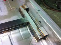
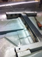
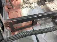
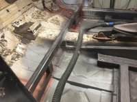
When repairing the frame rails, floor and rockers I noticed that the original frame rails tapered away behind the front seats. Given the sheet metal used for the seat mounts and the single layer steel ahead of the rear seat I concluded that reinforcement might be a good idea. I have heard of descriptions of the handling as being 'whippy' and figured that this might have been the cause.

Just imagining the possible movements both lateral and vertical it seems quite likely that the place where any movement might become evident is the transmission tunnel which could crease and buckle, not being a flatish structure.

My solution was three fold.

  • Continue the replacement frame rails to the front of the rear seats. The geometry means they stand proud in the rear footwell, but I planned for soundproofing to fill the gaps.
  • Replace the Single sheet metal cross piece in front of the rear seats with something more substantial and tie the frame rails into it.
  • Replace the single sheet mounts for the front seats with box section steel and again tie these in with the frame rails.
I used 2.5mm box section to make sure that it's really stiff but this might have been an overkill on reflection.

The proof of the effectiveness of this will be in the driving which hasn't take place yet. I guess it's added some weight and it's nowhere near original but I aim for this to be a frequently driven car so felt it was worth it.
 

Attachments

  • IMG_1333.jpg
    IMG_1333.jpg
    392.3 KB · Views: 148
  • IMG_1491.jpg
    IMG_1491.jpg
    413.6 KB · Views: 146
  • IMG_1565.jpg
    IMG_1565.jpg
    379.5 KB · Views: 141
  • IMG_1560.jpg
    IMG_1560.jpg
    432.4 KB · Views: 158
  • IMG_2027.jpg
    IMG_2027.jpg
    1.6 MB · Views: 147
  • IMG_2024.jpg
    IMG_2024.jpg
    1.8 MB · Views: 155
Erik,

While I was under there I took some pics of mine in case it is helpful to you.

From underneath it does not look unusual.

The white is just gaffer tape I put from inside the car to keep paint from going in there.
 

Attachments

  • file-7AE0D7FE-51FD-452C-9F30-C755BC55540D-3693-000003618EDAE968.jpg
    file-7AE0D7FE-51FD-452C-9F30-C755BC55540D-3693-000003618EDAE968.jpg
    173.8 KB · Views: 133
  • file-C942E031-AAE0-4BFF-A5ED-202BABEFD5A8-3693-000003618E5F135D.jpg
    file-C942E031-AAE0-4BFF-A5ED-202BABEFD5A8-3693-000003618E5F135D.jpg
    202.4 KB · Views: 138
Back
Top