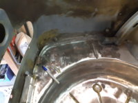
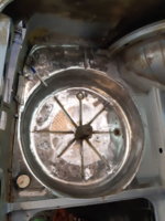
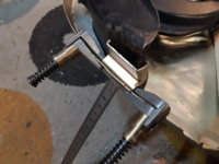
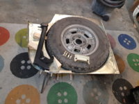
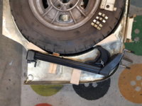
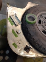
Whats this metal tab for next to the spare wheel well?

eriknetherlands

Moderator
Site Donor
Messages
3,038
Reaction score
2,283
Location
Netherlands, Eindhoven area
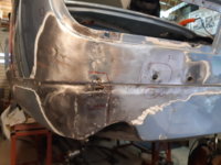
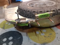
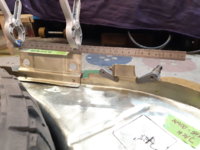
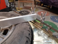
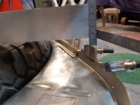
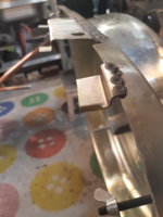
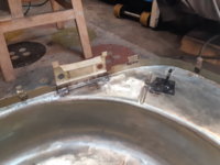
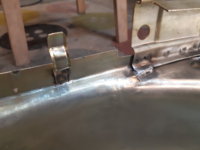
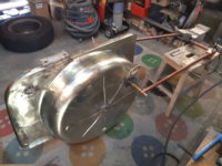
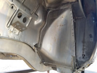
I'm contemplating taking the whole spare wheel well out to fix the crap in the corners ( see pics) .

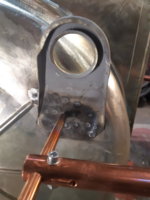
What is the purpose of the tab on the inside, at the pen tip, under the wooden floor?

Does it support the jack?
 

Attachments

  • 15625221255702231816589973254042.jpg
    15625221255702231816589973254042.jpg
    227.9 KB · Views: 490
  • 1562522167495998784130147029669.jpg
    1562522167495998784130147029669.jpg
    290.4 KB · Views: 466
  • 15625221888148863757227269582988.jpg
    15625221888148863757227269582988.jpg
    251.5 KB · Views: 392
Ok... so floorboard rest it is.
If the tab is to support the wooden floor panel then mine is about 25 mm /1 inch too low. Strange. I will need to take a closer look when im back home (out of country for a few days); it may got wacked at some point in its life. That corner of my car isn't its best side....

Anyone in a position to post a pic?

Im also interested learn about the exact location of the threaded post that holds the jack. I have 3 holes (that oncr were spotwelds?) but no threaded post.
Luckily it was available at the dealer 3yrs ago so if anyone can tell me where it should go, i'll weld it in.

Erik.
 
I just got my parts back from the plater, and it time to start welding again. For this, I need to get back to my question; the metal tab and its purpose.

The answers you guys gave me ("to support the wooden floor boards") satisfied me for some time, but now that I have everything clean and in pieces, I can 'Lego' it out and the 'floorboard' answer doesn't seem correct. It is simply 12 mm (1/2 inch) too low to carry the floorboard : the bumper reinforcement already has a flat surface in the middle that supports the wooden plates and that reinforcement is just 2 inches next to it. (The 2 special prongs pointing upwards grip the vertical trim panel around the rear lights.)

The metal tab also is not purposely added to act as a cable harness clamp, as these are generally different in the car (the omega shaped thingies). One of these dedicated wire harness tabs was just 2 inches next to the metal tab. So, holding the harness seems not to be its function.

The only thing I can guess is that it hold the foot end of the jack, to prevent it from denting the rear valance. Is that what it is supposed to do?

I've made some (a lot... ) of pics to help explain what I have.

I'd like to ask a second opinion if I may.
Regards,
 

Attachments

  • 20201103_173642.jpg
    20201103_173642.jpg
    235.5 KB · Views: 294
  • 20201103_173648.jpg
    20201103_173648.jpg
    224.8 KB · Views: 259
  • 20201103_173620.jpg
    20201103_173620.jpg
    315 KB · Views: 254
  • 20201103_173630.jpg
    20201103_173630.jpg
    332.4 KB · Views: 249
  • 20201103_213936.jpg
    20201103_213936.jpg
    279.3 KB · Views: 237
  • 20201103_214337.jpg
    20201103_214337.jpg
    304.2 KB · Views: 244
  • 20201103_214739.jpg
    20201103_214739.jpg
    254.3 KB · Views: 234
  • 20201103_214748.jpg
    20201103_214748.jpg
    274.7 KB · Views: 237
  • 20201103_214853.jpg
    20201103_214853.jpg
    179.7 KB · Views: 233
  • 20201103_215509.jpg
    20201103_215509.jpg
    300.8 KB · Views: 241
Last edited:
It is a tail light wire retaining tab. The reason it is bigger than the rest is because that is the exact spot where the wiring loom splits between driver and passenger tail lights.
 
Nice job I have a question as to where you got the metal tabs? or did you make them up?

Thanks, Rick

Hi Rick,
I fabricated them. It took me 10 hours to make them all.
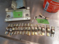
I made two rollers for my bead roller to press the shape in flat steel plate, basically making a continous strip with the bevelled edge. Then I cut strips of the correct length, and bend them around a custom mould to get the omega shape. I build the mould myself from some flat steel bars, and a section of thick round tube. Some welding and grinding required!
 
Just finished welding it all up, as close as factory as I could get it.

Spotwelds for the wheel pin, harness tabs, floorpanel supports and towing hook.
Mig welds + spotwelds for the bumper brackets.
 

Attachments

  • 20201109_230005.jpg
    20201109_230005.jpg
    183.6 KB · Views: 185
  • 20201109_230059.jpg
    20201109_230059.jpg
    229.3 KB · Views: 181
  • 20201109_230116.jpg
    20201109_230116.jpg
    182.9 KB · Views: 206
  • 20201109_224429.jpg
    20201109_224429.jpg
    314.4 KB · Views: 201
  • 20201109_224517.jpg
    20201109_224517.jpg
    238.1 KB · Views: 197
Beautiful work Erik!
Have you run into any areas where the spot welder will not fit (even though the factory welds are spot)? An example is the front frame rail to the inner fender panel. It seems to me that there is less than two centimeters within which one half of the spot welder would need to be.
20200925-spot welds.jpg
 
Beautiful work Erik!
Have you run into any areas where the spot welder will not fit (even though the factory welds are spot)? An example is the front frame rail to the inner fender panel. It seems to me that there is less than two centimeters within which one half of the spot welder would need to be.
View attachment 105292

I haven't cut open that part of my car, but it can be done I think.
In such tight corners one electrode is not much more the a piece of flat stock of copper stuck in the gap, and the other end is a normal finger. Having that gap behind it tells me it could be (was?) made that way.
A bit like how the rear wheel arches are spot welded; even less space there.
 
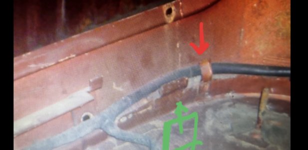
Just to document something on the original question; i found a car of a friend which still is in it's original condition.

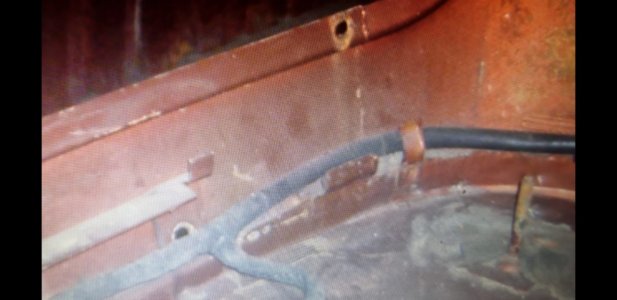
It has the same metal tab, as can be seen in the enclosed pictures.
Clearly seen is that the cable harness is retained by the standard cable clip, indicated with the red arrow.

The purpose of the wider part, identified in green, is still not clear to me. I'm still guessing that it's main function is to protect the cable harness against the foot of the jack to prevent that it pokes through the cables and create a short circuit.
 

Attachments

  • Screenshot_20211101-135556_WhatsApp.jpg
    Screenshot_20211101-135556_WhatsApp.jpg
    218.1 KB · Views: 132
  • 20211101_135938.jpg
    20211101_135938.jpg
    212.7 KB · Views: 172
Back
Top