DIY - A Wiper mechanism and Motor Restoration - drafting -

A few years ago I rebuild my windscreen wiper motor and associated mechanism.
Here's a few pointers for others endeavoring on the same path + a link to possibly needed spare parts.

Part of my knowledge comes from master @deQuincey who already deep dived into these components ~2010. Unfortunately Photobucket messed up the pics, so the combo of his knowledge and my new pics are the basis of the thread below.
(Links to Deq's original threads are in post #5 in this thread)

It's just my view, and I'm happy if others chime in and add or correct stuff.

Here to help & learn.
 
Last edited:
Dismanteling is fairly easy:
The wipers flip off the spline when the small tab under the arms is pushed.
(I believe post 10/1973 wipers have a securing nut instead of the small tabs?)

2 thin nuts on the window edge twist off, dropping the system. under the thin nut is a chrome domed ring with an alu washer that contacts the paint. keep track of the order of the parts.
The rubber buffer on the bracket on the motor is the 3rd point, that basically defines the pitch of the system, and therewith influences the pressure of the wipers on the window.
Disconnect the wires and the system just drops out.
20200612_205635.jpg
20201030_110035.jpg

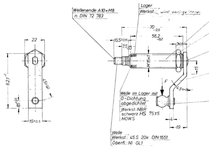
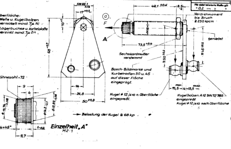
just a side note on the tech drawing and the parts: it seems that although parts 19&20 are drawn, they are actually never installed on our linkage systems. we think it is an error in the drawing. A few memebers checked, and also their parts do not have 19&20 mounted.
(reference: https://e9coupe.com/forum/threads/wiper-linkage-missing-part-in-my-system.35976/#post-302895)

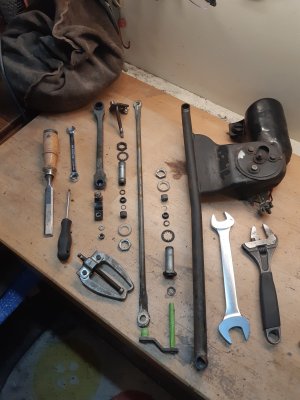
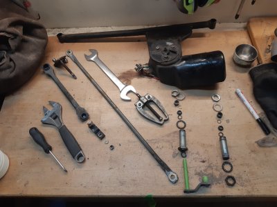
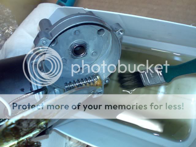
System on your workbench looks like this. (it's E9; E3 systems have a black tube with a kink in them - the rest is basically identical)
20200614_234343.jpg


Now you see 2 white plastic rings, and below them a thin nut again. Unscrew the nut, and the pivots drop from the black metal frame. Below the frame is a toothed spring ring and a 3rd flat nut:
20200615_000313.jpg
20200615_000404.jpg


Now do the same with the other spindle.
Then it's time to remove the linking bars, but before doing so, first note the relative position of the small arm on the motor relative to the motor's axis, as such:
20200615_002621.jpg
20200615_002616.jpg

The arm A and Arm B in my pics are almost in perfect alignment when in the rest position. I can't say if that's how it should be, it's just what worked for me during 4 years of daily driving.
I used a bearing puller to get the arm A off, and also used it on the staked splined ends on the tops of the spindles. Make sure you pull the splined part, and not the small plastic edge that is just 2 mm lower
20200615_001359.jpg
20200615_002820.jpg


The spindles have quite some parts, so do take care of al that comes out:
splined cap + ring/seal and plastic collar dust cap
20200615_003127.jpg
20200615_003144.jpg


Now you can pull the threaded bushes off the pin. The triangle part usually has a quite badly rotten pin, as it sits more in the rain zone under the grille:
20200615_003548.jpg
20200615_004755.jpg

Another wave washer is found at the base, between the arm and the threaded tube. Once the pin is out, another dust seal can be removed:
20200615_004817.jpg
20200615_003657.jpg


As I wanted to re-Zinc everything, i opted to unscrew the thin nut as well. I used soft Alu jaws in my vise to not damage the threads. I then noted how far on the threads it was located: 5 and 3/4 turns and it's off. (and thus needs 5 3/4's to get back in the right position). Some threaded tubes have thin nuts that are press-locked in place like these: I wouldn't try to seperate them, and just rezinc them as an assembly - this one was a used replacement part.
20200615_003932.jpg
20201103_223348.jpg


Notice: inside the tubes are smooth glide bearings: clean the inside and check their condition.
I had one tube with a broken bearing, thus i needed a used replacement part. I sourced a used sleeve with intact bearing through our lovely site.
In the pic below you see from R to L a fresh threaded section with it's slide bearing still inside. In the middle is a threaded tube but the bearing is out (was broken, see small piece) Left is a fresh spindle, with the slide bearing placed on the pin: this is also where the rotation occurs between the 6mm pin and the inside of this smooth glide bearing.
I think this slide bearing can be replaced with a generic off the shelf slide bearing: i didn't measure it at the time, but my guess is that a 6mm ID, 10mm OD and 10 mm high smooth bronze oil filled bearing will do just fine.
20201023_223527.jpg


Then it is on to the separation of the ball joints; they are just press fits. I used 2 different tools to flip the off:
A 24 mm spanner between the short arm and the triangle plate and a twist released that side.
20200615_010239.jpg
20200615_010306.jpg


I used a bearing puller to push the ball joint of the Arm A from the long tube:
20200615_011004.jpg


And here's the resulting parts pile:

20200615_013015-2.JPG


The Motor can further be separated from the frame by undoing the 3 bolts. The top side has 3 discs. Note the electrical tab under the bottom screw:
20200615_205213.jpg
20200615_205221.jpg


Underneath are 3 white plastic bushings and a rubber sheet:
20200615_205415.jpg
20200615_205449.jpg


The motor separates with 2 flat screws, allows for inspection of the carbon brushes. (would anyone know if they are available somewhere? these are typically also wear parts)
The rotor has 2 white plastic caps, 1 on both ends. Don't loose em.
20200615_211847.jpg
20200616_000103.jpg
20200615_212038.jpg


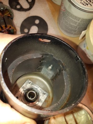
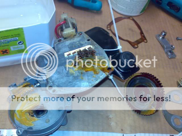
The connector side also has a casing that unscrews with 4 flat screws, underneath is 50 years old grease waiting to be replaced. This is also where the 3 drag contacts are located.
20200616_000040.jpg
20200616_000351.jpg


Inspect the gear for missing teeth or excessive wear; not sure what excessive is, but the teeth on my gear worked quite ok before pulling it apart (why did I even do this ...?) You can lift out the gear and clean it. I reinstalled with fresh grease afterwards.
20200616_000436.jpg
20200616_002614.jpg


Next up is clean, zinc & rebuild.
 

Attachments

  • 20200615_013015.jpg
    20200615_013015.jpg
    292.8 KB · Views: 46
  • 20200615_012537.jpg
    20200615_012537.jpg
    291.9 KB · Views: 15
Last edited:
Link to re-engineered parts by Waldemar on the German Forum


Looking at the build quality; I'd say these are 10X better then bmw original.

Waldemar asks around 400 euro, and he needs the ball joints + plates from your original part. (just relaying info from the german forum here, NMNA)

If you're in need, reach out to dear member @TomHom who will gladly assist as the middleman, as Waldemar isn't on our forum & not 100% comfortable dealing in english.
1741013182670.png

195916-30a53058f934ecb77fba2479d41e2608.jpg


For e3's the single ball joint part is still available through BTS autoteile:
(It's different(at least) in that the arm is straight vs double bend in e9 part)
 

Attachments

  • Screenshot_20250303_205433_Samsung Internet.jpg
    Screenshot_20250303_205433_Samsung Internet.jpg
    84.3 KB · Views: 17
Last edited:
  • Like
Reactions: Dlc
For the resurection of the system, it's basically a clean, rezinc and regrease action. If some of the moving parts are worn, then you'll have to source new parts. just post in the Parts section a "Want To Buy" thread.

Here's how i did it - I'm sure there are other ways that work as well.

I filled the plastic ball joint sockets with caulk to prevent damaging the plastic bushing during sandblasting. In the second part I did, I caulked in a screw so that the caulk came out easier.
20200615_204934.jpg
20200616_153626.jpg

20200616_154558.jpg
20200616_180410.jpg

Then later on it was all re-zinced while the plastic caps simply remain in place, as electroplating does not exceed 80 degrees Celsius most plastics remain ok.

Cut and stamped a new rubber sheet, as the original was torn: I used 1mm EPDM sheet.
20200619_092834.jpg


Rezinced part + some replacement (used) parts:
20201018_233838.jpg


assembled the pivots with their parts:
20201023_232209.jpg


order:
greased the pin, slide over threaded sleeve.
then install white plastic ring and brown collar ring
20201023_233100.jpg
20201023_233128.jpg
20201023_233211.jpg
20201023_233217.jpg


next step is pressing the spline part on with again a small ring inside. Stick the ring inside with some grease. Then press the cap on using a vice.
20201023_233243.jpg
20201023_233416-2.JPG
20201023_233512.jpg


As the splined cap needs to sit a bit over the pin to be able to re-stake the edges of the pin to mechanically lock the spline part, I used a ring to push the splined part a bit over the top of the pin. I made the stick-out 0,5mm:
20201023_234055.jpg
20201023_234125.jpg
20201023_234429-2.JPG


Next up is the reinstallation of the ball joints; a dab of grease to keep em alive for the next 50 years + a firm hand palm press to snap them back in place. I used a 3 washers to push the socket over the ball and into place.
20201024_000718.jpg
20201024_001135.jpg


2K paint of the frame in semi gloss black and lined up for further assembly:
The red pliers is the kind that have parallel closing jaws without teeth (plumbers use em often for delicate chrome parts): i used one to assemble (press) the ball joints on the short arm.
20201030_001353.jpg
20201030_091317.jpg


Further assembly of the hinge points:
20201030_091722.jpg
20201030_091843.jpg


20201030_091824.jpg
20201030_091828.jpg
20201030_091833.jpg
20201030_091843.jpg


and the other side (photographed upside down!): notice how the alu ring sits under, and almost hidden, the chrome ring? The body (lower window frame edge) is sandwiched between the white plastic and the alu ring.
20201030_110008.jpg


When I opened up the motor I noticed that one carbon brush was flipped sideways; must have happened during removal. I Repositioned the carbon brushe (btw quite long still - they must have some years left in them), Just added a dab of grease to the bearing bushes on both ends and close the sindle section up again. I cleaned out the old grease in the gearbox and replaced with fresh grease.
20201024_002107.jpg
20200616_002614.jpg


Don't forget to check that both white plastic caps at the ends of the spindle are not lost as they tend to fall out - stick em in with a dab of grease.
20200615_212038.jpg
20200615_212326.jpg


Reassemble with the 3 M6 bolts, and the small arm aligned on the previously made notch. When assembling the motor to the frame, take care of the orientation of the stepped white plastic washers (thin diameter on hood side, large diameter on road side). These 3 stepped washers are placed between the motor housing and the black frame. In the pic you see the rubber water cover that was introduced post '74; it's an earlier retrofit by me). Do not forget the 2 plastic white rings under the bolt heads and the 1 brass ground tab under the bottom bolt head:
20200615_205415-2.JPG
20200615_205412-2.JPG
20201030_160141-2.JPG


and Voila, the final result:
20201030_160141.jpg

Now all it needs is to finish the rest of the rust repairs....
 

Attachments

  • 20201024_002107.jpg
    20201024_002107.jpg
    263 KB · Views: 13
  • 20200615_205415.jpg
    20200615_205415.jpg
    258.6 KB · Views: 15
Last edited:
Here the link's to @deQuincey 's 2 threads that contain more information and in some cases other approaches / techniques / materials to give you some more options to tackle your own situation.

Link to his thread on the motor refresh::


And here's the link to his thread on the wiper mechanism:
 
(feel free to add - open for comments!)

Any observations on similarities / differences for the E3?
- ..

Any model year differences?
- up to 10/73 the spindles used the press on splined soft metal cap (in pic on the right) . Post 10/73 the wipers were held on with an M8 nut, thus the spindles have an M8 thread on it's end (in pic on left).
- additional rubber water splash guard for the motor post '74 (I think)
- ...

1741343685130.png
 
Last edited:
some further knowledge consolidation:
BMW apparently made spare parts that did not work well: in 2017 it was posted on the German E9 forum that some of their newer spare parts missed the edge under which the tab from the wiper grips that hold it in place. left pic with red car showing bad part. right image shows original part with the gap the exists between spined cap, and the threaded sleeve.
1741341451207.png
1741341826479.png
 
Secondly, remove the splined cap before offering it up for re-zincing (electroplating).
The soft metal cap gets destroyed by the acid of the plating process.
Left damaged; right old, used part for reference.

1741341928868.png

Side note: as the internal parts of the pivot are most prone to rusting, separation of the mechanism is advised anyway.
 
the cap cap be removed with a bearing puller, or you can fab something up like @JamesE30 did:
20200615_002820.jpg
1741342074809.png

James' self made part has a pointed screw to be able to pull the tab nicely over the top of the spindle.


When using a bearing puller, you may need to place a small part, like an M3 nut, between the center push pin of the puller and the spindle top if it doesn't pop off. It will allow the puller to pull the splined part beyond the end of the spindle top.
 
Last edited:
From the German Forum as well:
Here's the BOSCH drawing of the spindle part used up to 10/73.

It has some dimensions of the splined part:
72 teeth, and the spline is tapering from 14,2 _0,1 mm to 13,74_0,08 mm. No ID unfortunately if i read it correctly.

Also a drawing of the Post 10/73 part with it's M8 thread:
 

Attachments

  • M8 wiper pivot E9 post 73.png
    M8 wiper pivot E9 post 73.png
    81.4 KB · Views: 16
  • pre 74 wiper spindle.png
    pre 74 wiper spindle.png
    128.6 KB · Views: 17
  • Like
Reactions: Dlc
Final addition: the plastic bushings that are on the 2 metal arms can also be replaced if they are worn.
Thanks to member @BMW3.0CSi for finding the replacement parts:
1743091999912.png


White engineering
Wiperrepairs.com/wiper-bushings
Knockinane West,
Kilcummin,
Killarney,
Co. Kerry
IRELAND

You'll need 3x 12A bushings and 1x 16B.
Member BMW3.0Csi recommends to ask for Noel (from White engineering) for this because this is not a standard set. He also asked for only black bushings to match original BMW parts color. .

Link to his findings:
 
Back
Top