Fan blower switch

CookeD

Well-Known Member
Messages
265
Reaction score
11
Location
Providence, RI
Hey All, digging back into my E9 for some project work after a long hiatus. Good to be back.

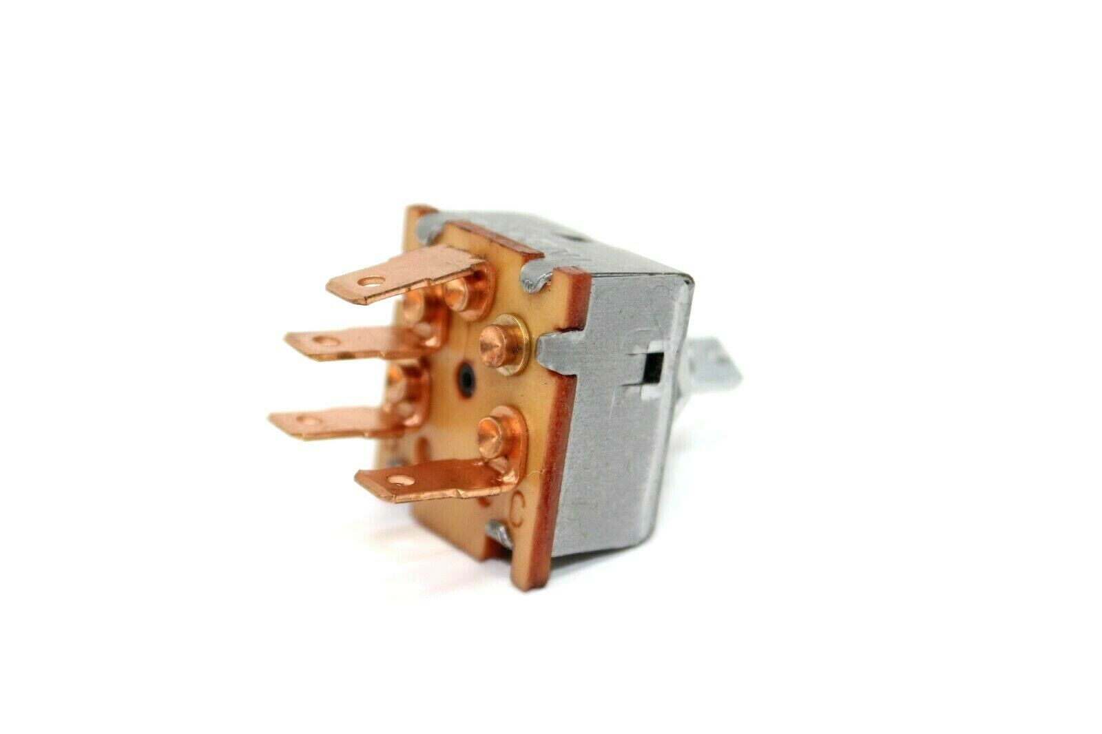
The first thing I'd like to do is solve my inop interior fan system (and if I could get my A/C back up and running that would be an added bonus...). I have a new temp switch, so good there for eventual A/C and to put that back in circuit. Is there a solution for the fan blower switch being NLA (see this link)?

Mine is pretty messed up and I don't think mine can be rebuilt, so wondering if there's a current best solution for at minimum getting some fan speeds..? I saw in a few posts that resistors need to either be eliminated or included in the circuit; I'm not a wiring genius, but hoping to utilize the OEM wiring if possible.

Thanks!

John
 
The indak 2 speed switch is cheap and good. Easy to wire in.
there is a dropping resister inside of your evaporator box - no need for a resistor style switch.

B10E4A99-96B8-4AC5-9A6D-B3E0740ABDE5.png
0168CB24-F07A-4385-8576-DB6BE4C05521.png
 
Are you adding a resistor?

2 speed switch is a plug in.

3 speed is not.

Did you do the math on the resistor you have and the resistor you will need?
 
since i have a '71 2800cs - this appears to be the correct A/C wiring diagram. if i go to the Indak 71r1167 two speed switch, i can eliminate the resistor between the a/c fan switch and the blower. this would make one think that the yellow green wire has no function as it connects to the black / white wire thru the resistor as only 2 wires go to the a/c blower (and one is brown). in looking at the a/c fan switch base (as shown in @sfdon 's picture in post #2) i have 3 wires - yellow / green, black / white + green / blue

1. green / blue is powered by fuse #8, so its important
2. yellow / green goes to resistor (question at hand)
3. black / white goes to other side of resistor, then connects to plug and on to the a/c blower
4. the diagram shows a black wire that comes from the changeover relay, connecting to the temp switch - going thru the plug and then hits the a/c fan switch. this is not in my base plug for the a/c fan switch ... and doesn't appear to have been removed. it might connect to the switch itself ... i have to look for the switch, its probably on the metal panel.

so in wiring the indak switch, looking at Don's pigtail connector (picture above), i would connect the yellow, black + green to the switch. that's self explanatory. my main question is that, removing the resistor, i'm trying to figure out what to do with the other end of the yellow / green wire.

i haven't found the #6 plug ... so i need to find the black wire (from the changeover relay to the plug ... and on to the a/c temp switch).

one thing i like about the newer diagram is that the compressor is powered from the battery, thru the aux fan relay + radiator fan switch - thru a diode ... and connects to the a/c temp switch and a/c fan switch on the black wire. this seems much better than the way shown in this diagram. bottom line is the power is coming the same way, but the diode changes things. the difference in Don's approach to power the temperature sender at the radiator is feeding it from the positive side of the coil rather tan running a wire from the fusebox.

1781468489787.jpeg
 
The yellow wire from the off/low/high Indak switch (L) goes to the resister in the evaporator- female spade on wire...
through the resister and comes out as a male spade at that resistor.
The black white wire female spade with two wires connects to it. This is how you operate the fan and AC at both low and high speeds.
Black white twin wires have a female spade that goes into a plastic connector cover to a male spade black wire and powers the fan which has a female spade connector.

The black wire at the Indak switch (H) is simply twinned at the same connector at the resister.

The black wire at the Indak (C) is common- it connects to the thermocouple.

Green wire goes to green/blue B+

Just four wires- off/low/high.


Just take the cap off the switch base and connect

Green (B) to Green/Blue

Yellow (L) to Yellow

Black (H) to Black/White

Black (C) common to thermocouple


We use butt connectors that we mis-shape a bit to make them fit tightly.
 
. the diagram shows a black wire that comes from the changeover relay, connecting to the temp switch -


wrong direction... the black wire operates the relay to turn off the heater blower fan.

It's a weird relay- normally closed and opens with B+
 
Don, while i get what you are saying about turning off the heater blower fan, on the 2800cs there is no circuitry in the fan to override the fan. there are only 2 plugs to the fan - a green / brown and a brown. the green / brown runs from fuse 9 to the heater blower fan and is grounded thru the heater fan control. very simple circuit with no other ways to control the override

i see what you are talking about, in the diagram below - the green / blue wire (instead of a black wire) that runs from the A/C fan switch to the heater blower fan ... but there are 4 wires on the heater blower fan (that is the problem for the 2800 cs. then i look at @alprada70 diagram of a/c, similar to the 74+ diagram - 5 wires from the temperature switch instead of 4 on the 2800cs ... on alprada's diagram there is also 5 wires on the temp switch ... and both have 4 wires on the heater blower fan (only 2 on the early 3.0cs and 2800cs.

ac wiring diagram - 2.png


ac wiring - alprada70.png
 
changeover and load shedding are there. i just saw the green / brown leading from the changeover to the heater blower fan on the 2800cs a/c diagram. the main wiring for 2800cs (USA) diagram that i have been looking at does not have the changeover relay on it - it shows the load shedding but no changeover.
 
Based on the diagram on Post #8 above, the resistor appears to create a difference between the full on continuously variable mode, and the switched max setting. So that would be a three position switch, with OFF, CONTINUOUS, and HIGH positions. Note there is another contact connected to the black wire that turns on the overall system. So this switch has FOUR terminals.

The swoop in the switch is there to indicate that that is a resistive trace inside the switch. The diagram is slightly misleading since technically the pin going to the green wire and to the resistor probably comes from the fat end of the swoop. As the switch is turned the current flows through more of the resistive swoop, so that will lower the voltage at the motor causing it to rotate more slowly. As you turn the switch the current goes through less of the trace, and there is more trace area (because the trace is fatter), All of which means less resistance, so the motor speeds up. If you turn the switch all the way, the the wiper engages the contact connected to the black and white wire, and this just shorts across the external resistor, causing the fan to run at full speed.

The resistor is there so that there is a small change in resistance between almost full on, and full on. The almost full part is continuously variable, and when you past the switch detent for the full on, the resistor gets bypassed and the fan goes to its highest setting.

The INDAK switch appears to be a two speed switch. Low, and High. It has the system-on contact.

In that setup, you presumably still have four wires. One is power (which would go to the green-blue wire on the diagram. Another is the system-on, which would go to the black wire in the diagram, and the other two go to the fan. I don't know if the switch as a resistor inside or not (I doubt it), so one of the outputs woudl go to the resistor (grey-green wire), and one would go to the fan (black-white wire). The resistor is sized to set the difference between low and high on the fan.

I am not sure what is up with the one in Don's pic, which only has three wires. In that one I woudl ignore the grey-green wire (tape it off so it doesn't short anything) and connect the thread pin to the black-white wire.

This page says that switch is a three position, two level switch...
 
Last edited:
I am not sure what is up with the one in Don's pic, which only has three wires.


Look closely - there are 4 wires!
 
Back
Top