so who knows the thread of the oil pressure sender?

rsporsche

Moderator
Site Donor $$
Messages
13,922
Reaction score
6,270
Location
Atlanta, GA
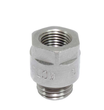
my understanding is that the thread is m12 ... but is it m12 x 1.75 or 1.25? i want to get an adapter for a separate vdo oil pressure gauge which has a 1/8" NPT female connector. so i need something like this

1782876306474.png
 
Neither. It’s m12x1.5
There is a VDO m12x1.5 available, but the standard source (discountguages) doesn’t have it. I ordered it from vehiclecontrols.com


I tried to order it from discount gauges but he said that it’s no longer made it seems so it’s just whatever stock people can find. This is for the two-post sender with the W and G posts
Initially I had that adapter and then ran a hose across towards the driver side for the actual sender but the hose was a bit faulty. In the end just got the sender and put it in directly into the cylinder head. The other problem with separating the sender from the head, especially with a hose made of rubber, is that you then need to separately ground the sender, since it’s usual ground is through the threads of the cylinder head.
 
okay - i will check to make sure i have that sender ... i was just under the impression that it was NPT not m12.
 
And I assume you meant MALE NPT sender above? For adapters if you already have the sender and it’s NPT I found that Titan Fittings has lots of options. Depending on what else you have around there the issue for me was sender is taller than the standard switch that came with the car and with the adapter it became too tall to fit without hitting the firewall.
 
i haven't tried to put the sender in there yet. and mine is NPT. so did the 360 007 sender not have any issue going in?
 
Went on perfectly. It’s not working correctly with the gauge at the moment but that seems to be a gauge issue / the sender is putting out the right signal - 0 ohm when off, about 116 ohm when engine running.
 
I am curious, where do you plan to mount the pressure gauge?

I picked up an extra clock a few years ago thinking that I might want to send it out for a Porsche pressure gauge retrofit, but have not pursued the project further.
 
I mounted my gauges below the radio since I don’t have AC. I’ll take a better picture once it’s fully in, still dealing with the oil pressure gauge. It registers zero correctly but then with engine on it rises all the way past the 80 psi mark even though sender is only showing 126 ohm. Gauge is supposed to respond to 0-180 ohm range.
1782918818842.jpeg
 
I mounted my gauges below the radio since I don’t have AC. I’ll take a better picture once it’s fully in, still dealing with the oil pressure gauge. It registers zero correctly but then with engine on it rises all the way past the 80 psi mark even though sender is only showing 126 ohm. Gauge is supposed to respond to 0-180 ohm range.
View attachment 221681

I did that too. Oil temp & Oil pressure senders, oil pressure sender was from La Jolla Independent.

Completed on.jpeg
Athena Interior 2023.jpeg
Gauge Panel 01.jpeg
Oil pressure sender.jpeg
Oil temperature sender.jpeg
 
Thanks guys, I have AC so the gauge mount in the center is not an option. The Alpina mount is possible, but I would still like to retain the speakers. I may begin looking into this again...

 
Oh that’s nice, hadn’t seen that option. If I had AC I would follow that lead. Looks nice and let
Us know how it goes
 
Thanks guys, I have AC so the gauge mount in the center is not an option. The Alpina mount is possible, but I would still like to retain the speakers. I may begin looking into this again...

Center mount is an option, but it requires a custom gauge plate:

20210213_161628.jpg
 
The three-gauge plus radio plate I have above is one I got recently from CS-Werk. It is very nicely made and fits perfectly if you don’t have AC and want to add gauges. I was initially planning to make a custom one like @Ohmess but then came across the prebuilt option
 
I mounted my gauges below the radio since I don’t have AC. I’ll take a better picture once it’s fully in, still dealing with the oil pressure gauge. It registers zero correctly but then with engine on it rises all the way past the 80 psi mark even though sender is only showing 126 ohm. Gauge is supposed to respond to 0-180 ohm range.
View attachment 221681
I assume one end of the gauge is connected to 12 volts, and the other is connected to the sender, which has some resistance to ground.

However, most of the 80 PSI VDO gauges I looked at are 240 ohms at zero pressure, and 33 ohms at 80 PSI. I see that VDO makes two different sender units, The 150 PSI unit is 10-180 ohms, but the 80 PSI unit is 33-240...

 
Perfect, we've gotten Scott in to help solve the electrical gremlins - should have alerted him from the start!
I'll lay out the info here so hopefully you can not only help me solve, but also the next person with the same problem.
The VDO sender has the following specs:

360-007 - VDO Sender 80PSI
VDO Pressure Sender

  • Max Pressure: 80 PSI
  • Warning Contact: 8.5 PSI
  • Voltage: 6V - 24V
  • Ohm Range: 10Ω - 180Ω
  • Thread: M12 x 1.5
  • Ground: Standard
  • Connection: 2x Knurled Nut
VDO gauge is the following:
VDO Series 1 Classic Chrome Bezel, Part #350-303 Oil Pressure,
0-80psi. 52mm (2 1/16") Diameter. Halo Lighted w/ White Pointer. 12 Volt.
Requires VDO 10-180 Ohm Sender.

So it would seem we have a match here - 80PSI max, 10-180 ohm sender and gauge
I have power to the gauge, the gauge is grounded and the sender is grounded through being screwed into the cylinder head.

My understanding is that the gauge is representing the ohmage it sees on this spectrum. 0 psi vs 80 psi is all just a measure of the sender and how much "signal" it sends for the pressure its rated to.
Here's the summary of my problem:

I have confirmed power going to the gauge and can get the light to work correctly. My issue is that when I turn engine on the gauge pegs at 80 psi. Troubleshooting I’ve done:
1. With sender attached to engine and no wire to the gauge attached to the sender, sender shows 10 ohms. With engine on sender is showing 127 ohm. I’m not sure where on the gauge 127 would correspond to but I imagine it’s less than the full 80 psi of the gauge, since I thought max was represented by 180 ohm.
2. With Key off gauge shows zero if sender wire disconnected which makes sense as it’s an open circuit. With sender wire attached gauge reads very low (near zero) in key off mode. With Key on engine off still the same. With key on engine running gauge goes right up to 80 psi.
By my understanding, that suggests bad gauge? It seems it isn’t representing the 10-180 scale correctly.

The response I got from gauge guy when I suggested maybe a gauge problem was the following, haven't yet had a chance to do, will do tonight:
Instance #1: I would agree, as Idle pressure well under 30psi.
Instance #2: Question why instrument would have any movement with sender wire attached in key off mode. Sounds like a small current is back feeding through sender/wiring, might some sort of grounding issue. Try disconnecting sender wire at sender, check if gauge is still just off zero stop. Then ,with key off, check for voltage at sender end of disconnected sender wire. Should be no voltage at sender result for this test. Had issue a few years ago, similar situation, sent out new gauge, same complaint. Turned out was a wire mis-labeled.

I realize the other thing I should check is that the gauge I have is the correct one - for various reasons I had ordered one of these in the past and then when I was going to use it, couldn't find it so I ordered a new one. The new one had a slightly different rear with different style connection terminals (spade vs screw-down Spin-lok). I had put that down to just a change within the same model (350-303), but as you note above, different gauges are set to different ohm ranges for different senders. I guess you really do need to match them correctly.
Here is the ohm curve for the 0-180 sender
1782931784823.png
 
Last edited:
The three-gauge plus radio plate I have above is one I got recently from CS-Werk. It is very nicely made and fits perfectly if you don’t have AC and want to add gauges. I was initially planning to make a custom one like @Ohmess but then came across the prebuilt option
Four gauges is overkill. I only did it because I wanted AFR, but once the Webers are tuned, you don't need to watch AFR all the time.
 
These gauges are what are known as "Galvanometers", so the meter movement responds to current. The more current flows through the movement, the more it moves.

Based on the resistance vs pressure characteristic of the sender, which has low resistance at low pressure, the overall circuit probably looks like this:


Screenshot 2026-07-01 at 12.57.11 PM.png


So, when the sender resistance is low, current gets split between the meter and the sensor, and as the sender resistance increases, more current flows through the meter.

Can you measure the resistance between the 12 V terminal of the meter, and ground, and between the sender terminal of the meter and ground? Also check the resistance between the body of the meter and ground (should be zero).

Based on this measurements, we should be able to A) determine if this is a correct meter for your sender, and B), determine a resistance to calibrate the two.
 
Back
Top