CSi CABLING CONNECTION QUESTION

LEO

Member
Messages
31
Reaction score
7
Location
BOGOTA COLOMBIA
Hi, I’m looking for some guidance and insight on the restoration of my E9 CSi, which has been disassembled since 2019… ;(

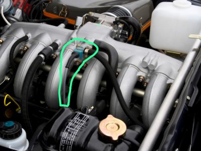
While restoring the wiring harness, we came across what might be the connection to this device. At this point it’s more of a suspicion, since we found it inside the front harness that connects the lights, the coil, and the relays located near the battery.

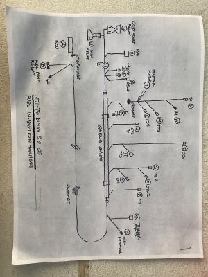
If anyone knows what this device is, what its function might be, and what the correct wiring should look like (in my harness the wires are crystallized), I’d really appreciate your help.

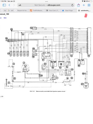
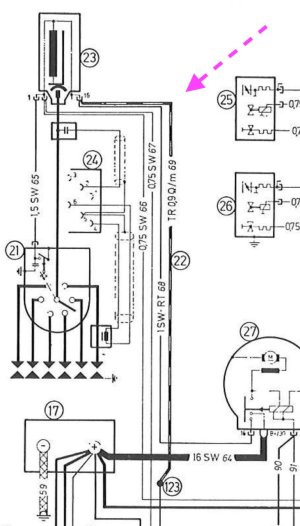
The two connectors are a bit confusing: one seems to go to ground, while the other has two wires of different colors that don’t let me clearly identify their origin, and the wiring diagram isn’t helping me much either.

I’m attaching a picture I found on the forum, highlighting the device that I suspect fits that connector.

Thanks in advance for any help.
Best regards,
 

Attachments

  • WhatsApp Image 2025-09-15 at 18.52.30.jpeg
    WhatsApp Image 2025-09-15 at 18.52.30.jpeg
    97.9 KB · Views: 61
Thanks, Chris. Do you know where I can find information about the wiring for that injector? Do you know if I’m right in associating it with that harness?
 
That is the cold start injector. My understanding is that one side is connected to the start circuit and the other gets grounded through the Thermo Time Sensor, which is mounted over near the thermostat housing
 
  • Like
Reactions: LEO
Hello Leo-

The picture is the Cold Start Injector.
Only 2 wires go to it and they come from the other side of the engine at the main engine harness tube above the valve cover.
The 2 wires go under the intake- not over.

Both wires are white and they both go directly from the injector to the Cold Start Relay at the brake booster area next to the main relay.

If you need I can explain how the time switch works.

In the schematic the injector is 159, the relay is 169, the temperature time switch is 160.
Power for the relay comes from pin 19 of the ECU and relay is triggered by the ignition switch (black wire at connector 168)
Keep in mind that almost all wires in the engine harness are white and have tiny numbers printed on them.

I will include a Csi injector schematic soon.

Send me a DM if you need more info- warning my Spanish is only so-so!
I am in Portugal this week and Spain next week.
 

Attachments

  • IMG_3081.jpeg
    IMG_3081.jpeg
    312.2 KB · Views: 40
  • IMG_3080.jpeg
    IMG_3080.jpeg
    702.5 KB · Views: 29
Thanks for your response and your super helpful input. I think I’m finally starting to piece together this puzzle that’s been apart for over 5 years, while also trying to understand several things… Turns out, the injector connector I found added into the headlight harness actually belonged to the injection harness, which indeed has all-white wires. Most likely, at some point during poor service, some “electrical genius” spliced it into a wire from the harness and swapped it around—reason why cold starts never worked properly. That said, I didn’t really start it too many times anyway… I decided to restore this car practically the very day I first drove it. Now we’ll get this sorted out. Thanks again for being open to DMs—I’ll try not to send too many, lol.
 
BTW- I worked in Colombia for 5 years. Know Bogota OK, Medellin better and the area around Rio Neche best. Zaragoza has a school I built for it.
A very small school! And I rode on the Metro in Medellin the first week it opened in 1995.
 
  • Like
Reactions: LEO

BTW- I worked in Colombia for 5 years. Know Bogota OK, Medellin better and the area around Rio Neche best. Zaragoza has a school I built for it.
A very small school! And I rode on the Metro in Medellin the first week it opened in 1995.
Honestly, you’re full of surprises! You can practice your Spanish with us — very few E9s made it to Colombia… Let me know if you ever come to visit, I’d be delighted to treat you to a bandeja paisa!
 
I’m continuing with my findings… and looking for logical reasons. Does anyone know why there is a transparent wire, #69, connected to the coil before the resistor? Any reason why it would be transparent? Does anyone know if there is a wire on the market that isn’t low-voltage (like speaker wire) but transparent? Maybe I’m being overly purist, but these are questions that someone might know the reason for, and why it was left this way.
 

Attachments

  • tr 0,9 :m 69.jpeg
    tr 0,9 :m 69.jpeg
    96.9 KB · Views: 21
I assume you have a model year 1974 CSi. That IS the resistor on a 74, it replaced the ceramic resistor on earlier cars. It drops the voltage to the coil to 9 volts.
To slightly clarify Chris's reply: If you look at the wire designation in the diagram you posted it says that wire is TR 0.9Q/m 69. (here I have used the letter Q to denote the actual symbol, which is an upper case Greek Omega). 0.9Q/m means 0.9 Ohms per meter. I assume TR means "transparent". So the wire itself is the resistor, and yes, it is a special wire, and not some guy's piece of cheap speaker wire. You should be able to disconnect one end and measure the resistance and the length and then see if it is in fact the right resistance.
 
  • Like
Reactions: LEO
@HB Chris and @ScottAndrews Friends, what an amazing explanation — yes it is a BMW 3.0 CSi VIN 4341353 was manufactured on October 23rd, 1975 and delivered on December 1st, I’m learning so much from you all! That wire is completely burned, so I’ll have to replace it. Do you know where I can find a proper replacement? It really is transparent almost yellowish transparent. And another question: should it then be about one meter in length? Thanks!!!
 
Dropping 3 volts with 0.9 ohms means a current of 3.3 Amps, which means the resistor is dissipating 9.8 watts, so I’d use a 20 watt resistor. Check Digikey or Mouser
 
  • Like
Reactions: LEO
Back
Top