As some of you know, I've been on a quest with heads lately. And as I tear them down, I am finding that the having the right tools will make my like easier. This has led me to BMW special tool #7003 - aka the iron maiden.
As seen here, it is what the blue manuals prescribe to remove the cam.

The trick is, you need to release/depress all of the valves simultaneously to allow the cam to make a clean getaway. Others have managed to circumvent the 'maiden by using a series of screwdrivers and wires. I considered this, but didn't feel it was as easy nor safe as just making my own tool - especially if I plan to do it more than once. At a minimum I imagine performing this operation at least (4) times. Two heads, disassembly and assembly. Following is a high level documentation of my build.
I may have overbuilt it. The frame is composed of 3/8" by 2" bar (~9,5mm by 50mm).

Tacked the frame.

And welded. Not my best work, but should be plenty strong enough for this tool.


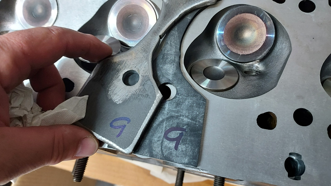
Then on to fabricating the "fingers" I used 1/8" by 3/4" bar (3mm by 19mm). Note the rounded edges - they become quite elegant later in the build.

Color example from an original BMW tool - found on the forum, maybe from @restart ?:

And here it is all painted. This is Rustoleum "Maui Blue" color - pretty close to the original photo. It's a little too clean at the moment.

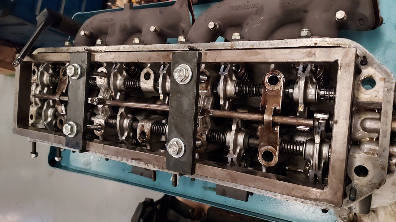
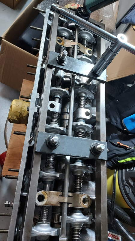
Here it is sitting on the head. The fingers engage the valve adjuster wheels.


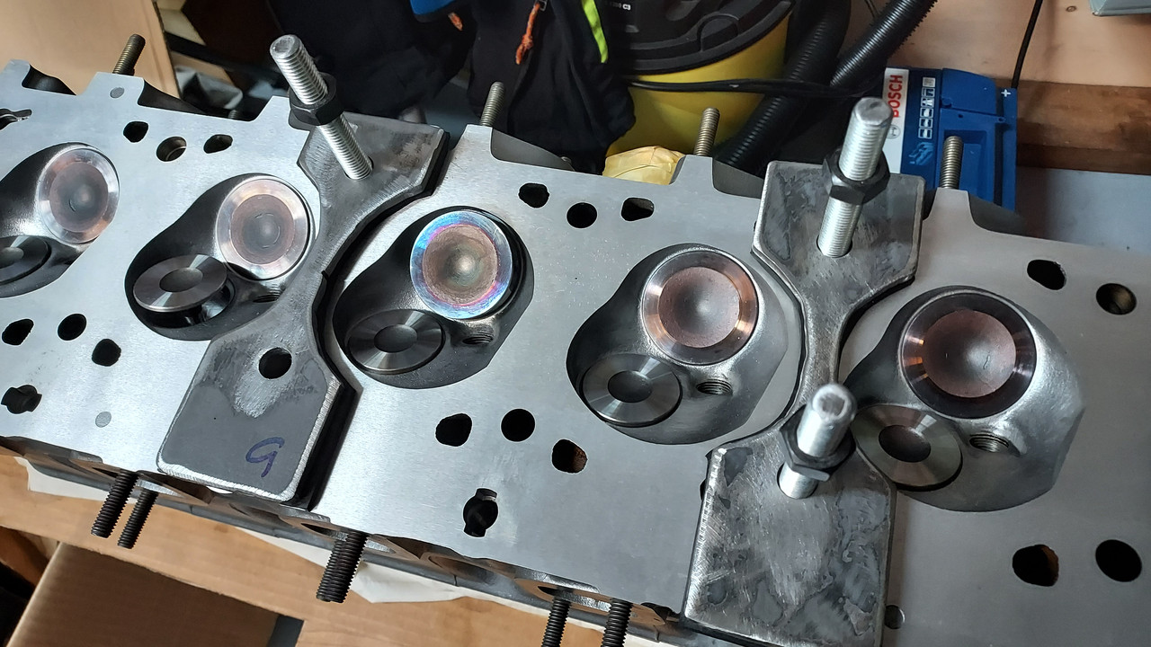
As the rockers are depressed, they rotate. The rounded edge of the fingers fit beautifully in the concave sections of the rocker arms.

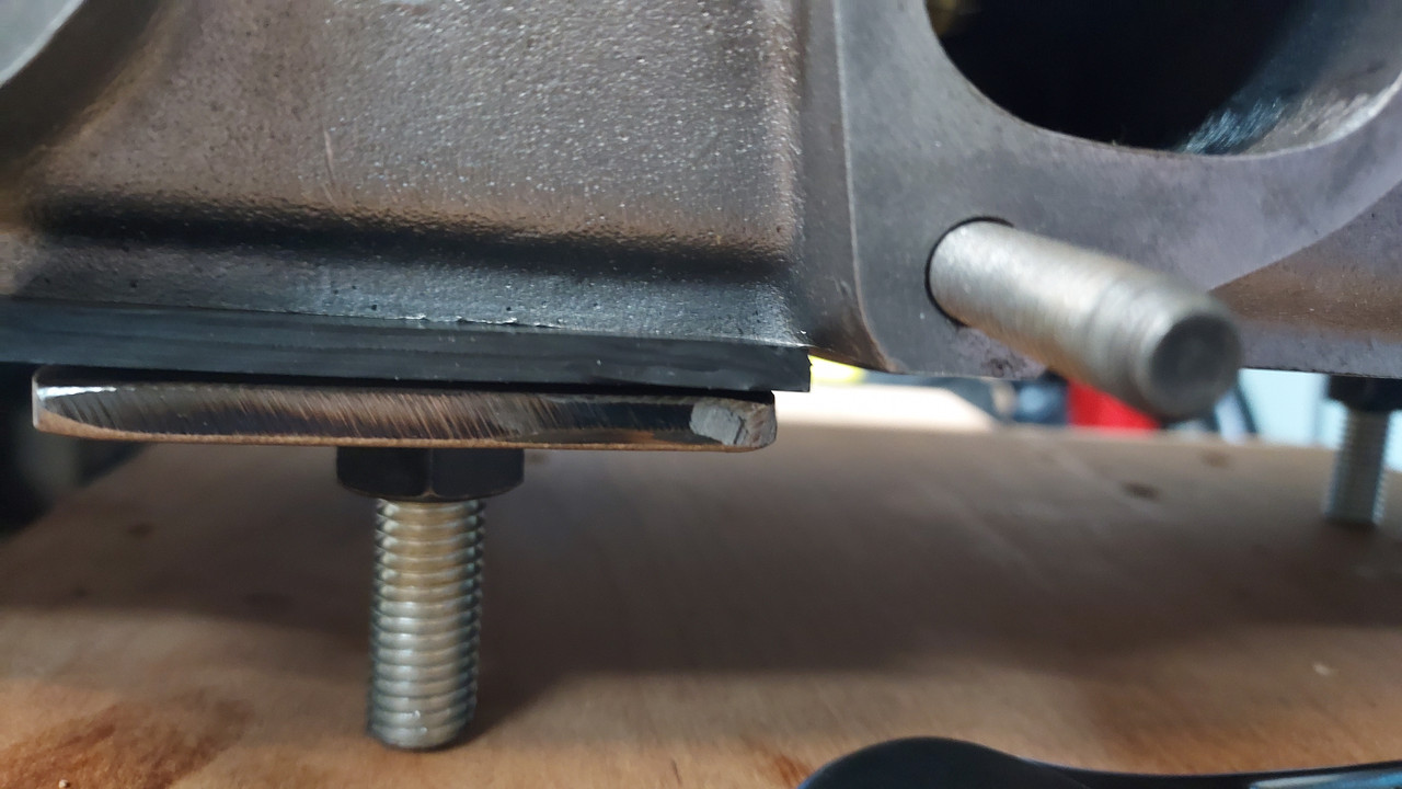
I polished the end of the fingers to they won't mar the surface of the valve adjuster wheels.

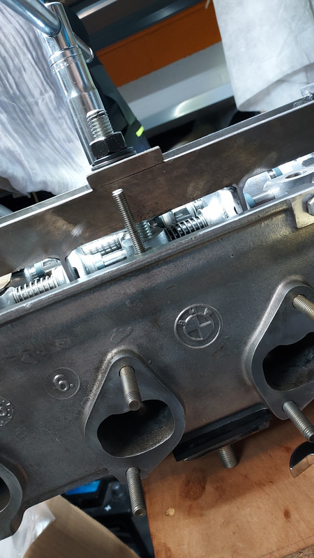
Arrow marks the front.


I will use (4) seperate bolts - not the head bolts - to operate the tool.
As seen here, it is what the blue manuals prescribe to remove the cam.
The trick is, you need to release/depress all of the valves simultaneously to allow the cam to make a clean getaway. Others have managed to circumvent the 'maiden by using a series of screwdrivers and wires. I considered this, but didn't feel it was as easy nor safe as just making my own tool - especially if I plan to do it more than once. At a minimum I imagine performing this operation at least (4) times. Two heads, disassembly and assembly. Following is a high level documentation of my build.
I may have overbuilt it. The frame is composed of 3/8" by 2" bar (~9,5mm by 50mm).
Tacked the frame.
And welded. Not my best work, but should be plenty strong enough for this tool.
Then on to fabricating the "fingers" I used 1/8" by 3/4" bar (3mm by 19mm). Note the rounded edges - they become quite elegant later in the build.
Color example from an original BMW tool - found on the forum, maybe from @restart ?:
And here it is all painted. This is Rustoleum "Maui Blue" color - pretty close to the original photo. It's a little too clean at the moment.
Here it is sitting on the head. The fingers engage the valve adjuster wheels.
As the rockers are depressed, they rotate. The rounded edge of the fingers fit beautifully in the concave sections of the rocker arms.
I polished the end of the fingers to they won't mar the surface of the valve adjuster wheels.
Arrow marks the front.
I will use (4) seperate bolts - not the head bolts - to operate the tool.