Dear Mike.
To my inexpert eye it seems very odd to have an earth cable to the sensor and then two outputs, i am more prepared to see an +12v input and then the 2 outputs one for 91 and the other for 99
Could you please confirm ?
What am i missing ?
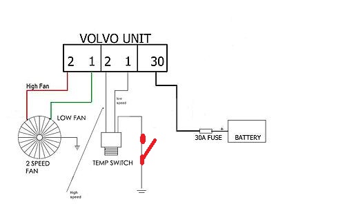
It is a switch, not a sensor. The switches are connected to a common wire on one side, so when each temperature limit is passed the associated switch closes and connects the input associated with it to the common wire. It would absolutely work with 12v on the common lead, but that's not what is needed in this case. In the Volvo link there is this schematic of the dual relay:
Note that the 12v needed to operate the circuit is present on A1, so we will need grounds to actuate the relays. When the coolant reaches 90°C, thermoswitch contact #1 closes and presents a ground to R1. This actuates the low speed ( left side ) relay with current provided through a NC contact of the High speed ( right side ) relay and the fan is started on low speed.
If the temperature continues to rise above 99°C, contact #2 of the thermoswitch will close, presenting a ground to R2 as well. The high speed relay ( right ) will actuate, providing 12v to the high speed winding as well as removing 12v from the low speed winding, resulting in high speed operation.
When the temperature drops below about 93°C, contact #2 of the thermoswitch will open, the high speed relay will drop out, and the fan will revert to low speed operation because of the NC contact on the high speed relay. When the temperature drops below about 84°C, the low temperature switch will open, the low speed relay will drop out and the fan will stop.
A serious advantage of this sequential operation is that the inrush current on the initial start of the fan is limited by the speed limiting resistor, much less likely to blow fuses and easier on all the contacts. Once the fan is running on low speed it is generating back EMF and the inrush current on the high speed actuation is also limited.