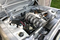
Just got the engine bay finished up. Started the new motor (3.5 l) for the first time last week (oil pressure came on within a few cranks after I installed the oil plug screw behind the filter mount). Ran the motor for a good 1/2 hour above 2,000 rpms to start the break in procedure. Next up will be the Megasquirt tuning. I tried to keep the spririt of the stock D-jet look, but made some changes to the engine bay (besides removing carbs): moved the batteries under the rear seat, placed the EFI fuse and j-box in the old battery location, installed an aluminum radiator, installed a 3 coil pack wasted spark ignition, built custom fuel rail to fit angled injector ports (did not want to mess with all those little hoses on barbed fittings), and added o2 and egt sensors to exhaust manifold.
You are using an out of date browser. It may not display this or other websites correctly.
You should upgrade or use an alternative browser.
You should upgrade or use an alternative browser.
Another EFI engine bay
- Thread starter Sven
- Start date
A bit too early to tell. Seems to run fine at idle and low rpm with no loads. I hope to be on the road in two weeks for tuning. I am in the process of finishing up the door and 1/4 window trims and glass (ranks up there on the PITA scale), then install the seats, dash (coming back from justdashes next week) and front window, then tighten all the suspension bolts under load and off to the alignment shop, then the open road...
nice,
congratulations
not for me, running for original, but nice work anyway !
enjoy !
wish you were soon in the road
congratulations
not for me, running for original, but nice work anyway !
enjoy !
wish you were soon in the road
pamp
Well-Known Member
Efi
Sven,
Is this your original car or another? You are certainly a wizard with this stuff and hope you trade notes with sfdon who is the guru of the California EFI modification scene. Your newest generation is by far cleaner than the last, the battery tray idea is cool and looks quite impervious to weather. You have enough in your photos to give me so many questions as to fill a manual. Can you tell me where you have located the O2 and EGR senders in the exhaust system? I am in the middle of doing a price / cost analysis of options to replace my exhaust and when I build I want to leave all options open for future mod's. My #1 problem at present is that shipping fees for any large pieces seem to exceed the price of the part(s) themselves.
May be down your way soon...PM if you please,
Allen
Makes me smile when I see such nice work......
Good for you.
Don
Good for you.
Don
O2 & egt
Allen,
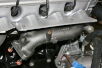
Here is a photo showing the front manifold.
Currently I have tapped a port into the existing boss on the manifold. First I cut a portion off to get the entry angle tilted upwards a bit. Then tapped it. This only works for the front manifold. The clearance is a bit tight at the rear manifold. I currently have the stock 3.0 exhaust installed. I will be going to a local S.S. exhaust and will have them add a 02 bung further down stream after all the pipes have come together. Alternatively, I may just install a second 02 sensor in the rear manifold. Not sure yet. So I just have to assume that the front 3 cylinders are behaving like the rear 3 cylinders. I would love to be able to do individual cylinder trim (MS can handle it - I would need 5 more EGTs, wiring, different manifolds, etc).
Each manifold also has an existing port for some diagnostic 02 sensor (where the brass colored plug is). I just drilled out the hole larger to fit an 1/8 NPT fitting for the EGT probe. Ideally you would want one for each cylinder close to the head port (30-40 mm). I have not tested the EGT yet. This is new for this go-around.
Allen,
Here is a photo showing the front manifold.
Currently I have tapped a port into the existing boss on the manifold. First I cut a portion off to get the entry angle tilted upwards a bit. Then tapped it. This only works for the front manifold. The clearance is a bit tight at the rear manifold. I currently have the stock 3.0 exhaust installed. I will be going to a local S.S. exhaust and will have them add a 02 bung further down stream after all the pipes have come together. Alternatively, I may just install a second 02 sensor in the rear manifold. Not sure yet. So I just have to assume that the front 3 cylinders are behaving like the rear 3 cylinders. I would love to be able to do individual cylinder trim (MS can handle it - I would need 5 more EGTs, wiring, different manifolds, etc).
Each manifold also has an existing port for some diagnostic 02 sensor (where the brass colored plug is). I just drilled out the hole larger to fit an 1/8 NPT fitting for the EGT probe. Ideally you would want one for each cylinder close to the head port (30-40 mm). I have not tested the EGT yet. This is new for this go-around.
Attachments
amazing work
ive seen sven's car (helped him put in the back window last weekend), and in my opinion, this will be one of the nicest coupes in the country when he's done - amazing work.
come on down pamp -we'd love to have you in town.
ive seen sven's car (helped him put in the back window last weekend), and in my opinion, this will be one of the nicest coupes in the country when he's done - amazing work.
come on down pamp -we'd love to have you in town.
pamp
Well-Known Member
Thanks
Alan...so cool that you guys could hook up as you both share the "passion" and I often need that extra set of hands! That said...as I am sure we have Don's attention and he has been very patient with me as I review options...I am a nuts and bolts tug engineer, and am trying to re-learn the auto circuitry deal! (degreed in 1976) Here is a shot of the 3.5 manifold(s)
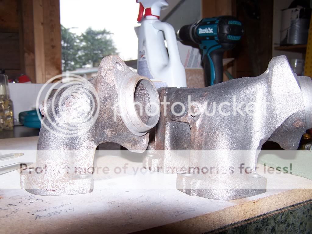
Of note would be that they have the two bolt flange. I see you have the three bolt...3.0 manifolds. This may be a worry for port matching to the 3.5. Also, the 3.0 down pipes are 1 5/8'' vs 2'' for the 3.5. One other thing is that the 3.5 manifold has a plugged port perfect for install of a pyro probe (egt) I am sure others will pipe in (forgive the pun) Dinner on the table, more on this later...
Measuring I see an aproximate port size for the 3.5 manifold as 1 3/8'' I am considering using headers of this tube size. I believe that for my own 3.3 this will work with the stock cam. The plan at present is a two into one merge then to single 2 1/4 pipe and mufflers much has been done by DaveG. My bung(s) will be at the merge point (single) No sustained redline RPMs so the EGT will not be neccesary for the present application. I may also build, again to DavidG's spec, a set using the cast manifolds and the 635 down pipes to the aforementioned two to one merge. Anyway, once both sets are fab'ed, ceramic coated. Then to testing...I am sure others have been down this road I am looking forward to input. I may end up investing more than a coupeking set up once all is said and done, yet the end may justify the means, you cannot stop learning.
Alan...so cool that you guys could hook up as you both share the "passion" and I often need that extra set of hands! That said...as I am sure we have Don's attention and he has been very patient with me as I review options...I am a nuts and bolts tug engineer, and am trying to re-learn the auto circuitry deal! (degreed in 1976) Here is a shot of the 3.5 manifold(s)
Of note would be that they have the two bolt flange. I see you have the three bolt...3.0 manifolds. This may be a worry for port matching to the 3.5. Also, the 3.0 down pipes are 1 5/8'' vs 2'' for the 3.5. One other thing is that the 3.5 manifold has a plugged port perfect for install of a pyro probe (egt) I am sure others will pipe in (forgive the pun) Dinner on the table, more on this later...
Measuring I see an aproximate port size for the 3.5 manifold as 1 3/8'' I am considering using headers of this tube size. I believe that for my own 3.3 this will work with the stock cam. The plan at present is a two into one merge then to single 2 1/4 pipe and mufflers much has been done by DaveG. My bung(s) will be at the merge point (single) No sustained redline RPMs so the EGT will not be neccesary for the present application. I may also build, again to DavidG's spec, a set using the cast manifolds and the 635 down pipes to the aforementioned two to one merge. Anyway, once both sets are fab'ed, ceramic coated. Then to testing...I am sure others have been down this road I am looking forward to input. I may end up investing more than a coupeking set up once all is said and done, yet the end may justify the means, you cannot stop learning.
Last edited:
manifold sizes
Yes, I am a bit fuzzy/confused on what the best exhaust setup will be. The 3.0 manifolds may not be the final solution. I ended up throwing the 3.5 manifolds away at the recyclers (oops). A 2" diameter down pipe is a 50% increase in pipe area from the 1-5/8". The upsize from the 3.0l to the 3.5l engine displacement is about 17%. Not sure if there is a linear relationship between area and displacement. At what point does the 3.0 manifold become constrictive? Above some HP threshold? I may end up compromising and running 2-1/4" from the bottom of the downpipes to the tail.
Yes, I am a bit fuzzy/confused on what the best exhaust setup will be. The 3.0 manifolds may not be the final solution. I ended up throwing the 3.5 manifolds away at the recyclers (oops). A 2" diameter down pipe is a 50% increase in pipe area from the 1-5/8". The upsize from the 3.0l to the 3.5l engine displacement is about 17%. Not sure if there is a linear relationship between area and displacement. At what point does the 3.0 manifold become constrictive? Above some HP threshold? I may end up compromising and running 2-1/4" from the bottom of the downpipes to the tail.
pamp
Well-Known Member
OK
Rats...those manifolds are $270 ea. new. Worth a dumpster dive for sure (how I have mine!)
Not having the day to day experience of others who have had the opportunity to try different combinations...suffice to say that I would use what was german designed as a starting point.
Not too tough to figure out volumetric if you decribe the engine as a pump, in and out being unobstructed. Complicated when you bring all together in consideration...intake volume, valve sizing, cam durations, porting, etc. Hence, the dyno and trial and error. Gotta have vacuum for the brakes to work, so going "stove pipe" on a normally aspirated engine doesn't work well on the street, fine for turbo apps. Probably talking out my butt here, yet what I have measured for the 3.0 is an aproximate size of 1 1/4'' inlet for the stock cast manifolds with a down pipe of 1 5/8'' The 3.5 aprox. 1 3/8'' to the 2'' down pipe. Seen headers 1 1/4''..1 3/8''..1 1/2''..& 1 5/8'' tube sizes. Mild to wild. Figured I would be safe for the 3.3 w/ 1 3/8'' to 2'' and open it up from there. Of note...I have been talking with Korman on these very same issues and will have more definatative data soon.
Last edited:
Beautiful work!
Sven , Outstanding work.
The radiator fits with the stock mounting brackets, but looks custom build...
Tell use more about it.
Thanks Barry
The radiator fits with the stock mounting brackets, but looks custom build...
Tell use more about it.
Thanks Barry
TodB
Well-Known Member
exhaust manifolds
Sven, your coupe is stunning!
At the risk of thread hijacking, I have a pair of stock exhaust manifolds from my E28 5 series that just came off if you are looking.
Sven, your coupe is stunning!
At the risk of thread hijacking, I have a pair of stock exhaust manifolds from my E28 5 series that just came off if you are looking.
Radiator
Barry,
The radiator was built by NameLessPerformance in southern WA. I sent him my original and be made one up. He did not quite get it right the first time. Second time fit perfectly. The radiator tanks really need their shape to clear the left frame rail and the right upper mounting bracket inner screw. At the bracket mounts he welded a 1/4" bar on one side and 1/2" bar on the other. Cooling works great so far. It is not as crisp looking as a stock radiator.
Fired up Jon's car today for the 1st time with megasquirt and wasted spark... It is humbling to see how fast the auto tune takes care of everything. Guess we drove 2-3 miles and covered 1/2 the fuel map. Tremendous reaction to throttle with immediate response on fuel ratio. Seems like all the cars I have done were the same- barely get them running and within an hour the smile is on your face. Have fun Sven!
Very nice Sven. Love the clean and simple look.
I looked high and low and can't seem to locate your intake air temp sensor.
I like the way your coil pack is mounted. Is it heat shielded?
I am assuming it is one of the Bosch units with everything built in into one assembly.
If your coil pack can endure 2ms spark duration I have a new ignition table you can try out when you are up and running.
Dave,
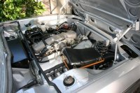
The air temp is seen in the second photo. Look on the rear right side of the intake log - just behind the bottom of the angled idle valve. I tapped a threaded hole on the same boss as the 'V' mounting bracket. There may have been a port there don't remember. The sensor is one from DIYautotune.
My MS is set at 1.5 ms max spark duration. How would I tell if it could be longer? I thought all this meant is that the next spark cycle could not begin for 1.5 ms, not that the actual duration of the spark is that long. This should only be an issue at high rpms.
The coils are not heat shielded. Do you think that is an issue? The unit is 3 coils together - a Bosch unit.
Yes, I would like to compare your current spark map to the one you sent me a while ago. I will be hitting the road in about a week to start testing/tuning.
Dave,
My MS is set at 1.5 ms max spark duration. How would I tell if it could be longer? I thought all this meant is that the next spark cycle could not begin for 1.5 ms, not that the actual duration of the spark is that long. This should only be an issue at high rpms.
The coils are not heat shielded. Do you think that is an issue? The unit is 3 coils together - a Bosch unit.
QUOTE]
1.5ms is pretty close. You should be able to look up what is the optimum setting for your coils via Bosch specs. Most stock coils cannot handle longer than 1ms. We use Electromotive DFU coils as it is fully adjustable to just about anything. With high compression or under high boost we tested various duration and came to the conclusion that it performs best all around at about 2 - 2.5ms.
When the radiator sheds heat it will deflect off the front of the engine, that is why stock distributor cap comes with the plastic cover. Being the odd shaped item that sticks out front it will catch all deflected heat wave. During the summer it will heat soaked and reduce the efficiency of the coils if not shielded from direct exposure.
David