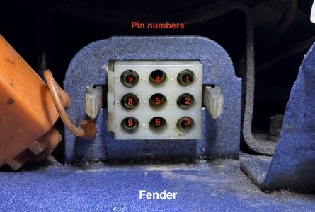
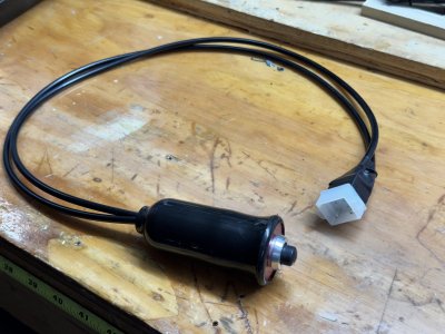
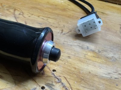
I was in the process of building a little ignition switch bypass using the diagnostics port (thank you @Stevehose ) and was researching which pins to use. Since it wasn't in any easy to find location I figured I would do a little post about it in case it is helpful for someone else. This is the 9 pin port with the orange cap located between the relays and brake fluid reservoir

Pin assignment: (in part from @decoupe)
1. RT : Battery positive
2. GN : Ignition on
3. BR : Negative (chassis ground)
4. Empty
5. Empty
6. Empty
7. SW or WS-SW : Starter
8. BL : Charge (alt light)
9. SW or GN-BR : RPM/Dwell
Diagram:

31: diagnostics plug
17: Battery
27: Starter
29: Unrelated connector for the black wire from pin 7 to piggy back on its way to the starter
Pin 1 goes to battery positive

Pin assignment: (in part from @decoupe)
1. RT : Battery positive
2. GN : Ignition on
3. BR : Negative (chassis ground)
4. Empty
5. Empty
6. Empty
7. SW or WS-SW : Starter
8. BL : Charge (alt light)
9. SW or GN-BR : RPM/Dwell
Diagram:
31: diagnostics plug
17: Battery
27: Starter
29: Unrelated connector for the black wire from pin 7 to piggy back on its way to the starter
Pin 1 goes to battery positive
Last edited:


