While I'm waiting for my new triple core Mark Preisendorf radiator to arrive, I thought I'd deal with some other cooling system odds and ends.
Most of us E9 owners are aware that our cars do not have a conventional heater contol valve that shuts off the flow of coolant through the heater core. Instead, the core is always plumbed, and the heater lever merely opens and closes the flaps on the heater housing. In hot weather, many of us can feel the heat coming off the heater housing. The a/c systems in these cars, never great to begin with, can certainly do without this extra heat load right next to the a/c evaporator.
There have been threads (http://www.e9coupe.com/forum/showthread.php?t=8581&highlight=heater+valve) discussing what is necessary to bypass the heater core. The quick and dirty way is to simply disconnect the two heater hoses from the heater core pipes that protrude through the firewall and splice them together. For those living in hot climates, this is fine, but here in New England, on those spring drives, I USE my heat. A second approach is to install a valve, like in a 2002, that simply stops the flow of antifreeze into the core. However, there is concern that this approach, which does not allowing the coolant to circulate, may cause overheating problems. Clearly what is needed is a full heater bypass valve that, when opened, sends coolant through the core and, when closed, bypasses the core without blocking the flow.
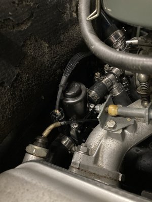
For reference, the hoses into the firewall are shown below (hose clamps removed). The top hose goes to the back of the head. The bottom hose (on my L-Jet M30B32) feeds the metal pipe that runs under the intake manifold.


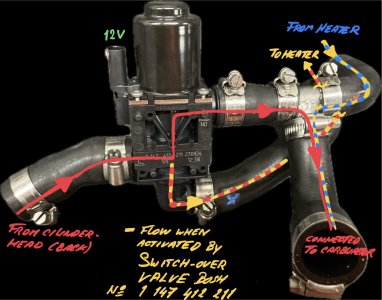
It is easy to imagine the valve that we need. It is shaped like a letter H. The top legs of the H are connected to the heater pipes at the firewall, and the hoses go into the bottom legs of the H. When the valve is open, it should block off the center section but allow coolant through the legs to and from the heater core, and when the valve is closed, it should bypass the core by diverting the coolant coming up the left leg, through the center section, and out the right leg. But how do you locate one the right size, and what adaptations to you need to do to make it work in the E9?
In a perfect world, we'd find a bypass valve that:
--Has 3/4" pipes (this is the size of the heater pipes protruding through the firewall)
--Has a 1.5" center-to-center (2" edge-to-edge) spacing between the pipes (this is the spacing of the heater pipes protruding through the firewall)
--Is metal
In practice... one out of three ain't bad, and close is good enough for horseshoes and hand grenades.
To locate a usable valve, I went on eBay, typed in "heater control valve," and spent an hour looking at lots of pictures, eventually finding three that are widely available through both the AC Delco and the Four Seasons cataloges. They're all cheap (less than $35). Because it's impossible to tell what will work and what won't until you actualy test-fit them, I simply bought all three. I think the total bill was about $60.


Note that all three of these have a lever on the end of the valve, which is, in turn, actuated via a vacuum dashpot. So in order to change from the heat to the no-heat setting, you could either remove the vacuum dashpot and simply move the lever (or wire it in position), or leave the dashpot installed and connect and disconnect it from the intake manifold to flip between enabled and bypassed.
Note also that, to connect any of these three candidate bypass valves to the two heater hoses, the heater hoses need to be either trimmed or lengthened.
AC Delco 15-5533
Verdict: This should work.
Advantages: The pipes are almost exactly the same spacing as the heater pipes, allowing clean attachment to the pipes on the firewall.
Disadvantages: The pipes are 5/8", not 3/4". And it's plastic.


The first one is AC Delco 15-5533 (Four Seasons 74781). This is not a classic "H" shape, but it has two inlets and two outlets. The one I bought came without the vacuum actuator, so the lever controlling the valve is plainly visible and completely exposed. In this picture, the flow of coolant in is supposed to be from the top right. The tube size is only 5/8" instead of the correct 3/4", but you can snug the hoses down with hose clamps. And, the spacing of the two tubes on the left is about 1.5" center-to-center -- almost exactly the spacing of the two heater pipes on the firewall. Unfortunately, the part is plastic -- an anathema to those of us who pride that our E9s don't have the plastic junk endemic in the cooling systems of newer BMWs.
The pic below is a test fit of this valve using two short 3/4" rubber hose sections to hold it onto the firewall. In order to have clearance for the lever, the lever must go on the left (away from the intake manifold). This forces you to install the valve upside down from the previous photograph, so the inlet side is lower left, where you can just barely see it. The outlet side is plainly visible upper left. The hose going to the metal pipe under the intake manifold is swung to the side. The hose coming from the back of the head is not visible.


In the photo below, I've swung the outlet hose back toward the valve so you can see that the natural elbow in this hose will allow the excess to simply be cut and the hose connected (I have not yet cut it; this is a test fitting). The hose from the back of the head will need to be lengthened with a 3/4" barb coupling and brought into the inlet at lower left (not visible).


So you can see that this should work. If you look up this part number on line, you'll see the vacuum actuator bolts on top of the lever, so it would be on the left. It looks like there's sufficient room for it.
AC Delco 15-5543
Verdict: This should work.
Advantages: The pipes are 3/4". And it comes with hoses on it, allowing quick attachment to the heater pipes on the firewall.
Disadvantages: The pipes are slightly too far apart. And it's plastic.


The next one I tried is the AC Delco 15-5543 (Four Seasons 47607). This looks to be exactly what you need, although, like the 5533, it is plastic. The pipes are 3/4" -- the right size. It's H-shaped with the actuator on the top. It even comes with two 4" sections of 3/4" hose on the ends, allowing quick attachment to the heater pipes. The inlet end isn't labeled, but I assume it's the one opposite the valve, or upper left, In this first pic below, I do a quick test fit. The 4" rubber hoses are longer than they need to be, so it sticks out a bit far.


Below I've trimmed the 4" hoses down to about 2". Unfortunately the pipes on this valve are slightly further apart than those on the firewall, and the shorter you cut these hoses, the more difficult a time they have mating up securely to both sides. Also in this pic, I swing the hose from the intake, showing that, like with the 5533, it looks like this hose can simply be cut just after it makes its elbow turn and then clamped directly to the pipe. Also, as with the 5533, the inlet hose from the back of the head (not pictured) need to be lengthened in order to be connected to the valve. The vacuum actuator can be taken off and the lever flipped manually, or if you like, the actuator can be used to close the valve; just hook a vacuum line to the intake manifold.


AC Delco 15-5302
Verdict: I have my doubts.
Advantages: It's metal.
Disadvantages: The pipes are slightly too far apart. One pipe is 3/4", the other is 5/8". There may be clearance issues.


I looked long and hard for an H-shaped metal valve, and this was the only one I could find. Initially I thought it was The Grail, but the vacuum actuator is on the side, and valve, pipes, and the vacuum actuator sit at an angle with respect to each other. Further, what is marked as the inlet tube is 5/8" whereas the outlet tube is 3/4". Also, the outlet and inlet tubes extend unequal distances. Individually none of these are showstoppers, but they make a clean installation challenging. In the pic below I have the valve cajoled into hanging there on the firewall. You can see that the tubes are slightly too far apart to mate cleanly with the firewall tubes, though slightly longer stub hoses would solve this problem. In this position, this could work, but technically the flow arrow is pointing the wrong way.


In the pic below, we turn the valve around so the flow arrow is pointing toward the heater, and you can see that there's a clearance problem, with the body of the valve hitting the #6 intake plenum.


So, it looks like either of the two plastic bypass valves -- the 5533 and the 5543 -- will work. As much as I dislike putting plastic in the cooling system, unless I can find a better metal bypass valve, I'll likely go with one of these. Plus, the color and the look and feel of the metal valve, to me, are somewhat at odds with the rest of the rest of the engine compartment. Of the three, interestingly, the 5533 seems to be the least visually intrusive. The 5543 is a quicker and easier adaptation, but that vacuum dashpot is sitting pretty high and looks fairly un-BMW-like (of course you could take it off). On the 5533, the dashpot unscrews, but on the 5543, it is a more integral part of the assembly, not as easily removed.
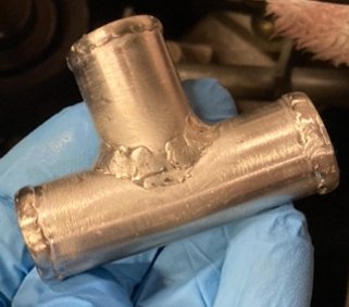
To finish up the adaptation and extend the inlet hose from the back of the head, I've ordered a length of Gates 5/8" heater hose (28491, $10.03 at Amazon) and Gates 3/4" heater hose (28492, $9.64 at Amazon), and several brass right angle 5/8" and 3/4" fittings (eBay; PEX fittings look like they'll work).
I'll amend the post when the final installation is done.
--Rob
Most of us E9 owners are aware that our cars do not have a conventional heater contol valve that shuts off the flow of coolant through the heater core. Instead, the core is always plumbed, and the heater lever merely opens and closes the flaps on the heater housing. In hot weather, many of us can feel the heat coming off the heater housing. The a/c systems in these cars, never great to begin with, can certainly do without this extra heat load right next to the a/c evaporator.
There have been threads (http://www.e9coupe.com/forum/showthread.php?t=8581&highlight=heater+valve) discussing what is necessary to bypass the heater core. The quick and dirty way is to simply disconnect the two heater hoses from the heater core pipes that protrude through the firewall and splice them together. For those living in hot climates, this is fine, but here in New England, on those spring drives, I USE my heat. A second approach is to install a valve, like in a 2002, that simply stops the flow of antifreeze into the core. However, there is concern that this approach, which does not allowing the coolant to circulate, may cause overheating problems. Clearly what is needed is a full heater bypass valve that, when opened, sends coolant through the core and, when closed, bypasses the core without blocking the flow.
For reference, the hoses into the firewall are shown below (hose clamps removed). The top hose goes to the back of the head. The bottom hose (on my L-Jet M30B32) feeds the metal pipe that runs under the intake manifold.
It is easy to imagine the valve that we need. It is shaped like a letter H. The top legs of the H are connected to the heater pipes at the firewall, and the hoses go into the bottom legs of the H. When the valve is open, it should block off the center section but allow coolant through the legs to and from the heater core, and when the valve is closed, it should bypass the core by diverting the coolant coming up the left leg, through the center section, and out the right leg. But how do you locate one the right size, and what adaptations to you need to do to make it work in the E9?
In a perfect world, we'd find a bypass valve that:
--Has 3/4" pipes (this is the size of the heater pipes protruding through the firewall)
--Has a 1.5" center-to-center (2" edge-to-edge) spacing between the pipes (this is the spacing of the heater pipes protruding through the firewall)
--Is metal
In practice... one out of three ain't bad, and close is good enough for horseshoes and hand grenades.
To locate a usable valve, I went on eBay, typed in "heater control valve," and spent an hour looking at lots of pictures, eventually finding three that are widely available through both the AC Delco and the Four Seasons cataloges. They're all cheap (less than $35). Because it's impossible to tell what will work and what won't until you actualy test-fit them, I simply bought all three. I think the total bill was about $60.
Note that all three of these have a lever on the end of the valve, which is, in turn, actuated via a vacuum dashpot. So in order to change from the heat to the no-heat setting, you could either remove the vacuum dashpot and simply move the lever (or wire it in position), or leave the dashpot installed and connect and disconnect it from the intake manifold to flip between enabled and bypassed.
Note also that, to connect any of these three candidate bypass valves to the two heater hoses, the heater hoses need to be either trimmed or lengthened.
AC Delco 15-5533
Verdict: This should work.
Advantages: The pipes are almost exactly the same spacing as the heater pipes, allowing clean attachment to the pipes on the firewall.
Disadvantages: The pipes are 5/8", not 3/4". And it's plastic.
The first one is AC Delco 15-5533 (Four Seasons 74781). This is not a classic "H" shape, but it has two inlets and two outlets. The one I bought came without the vacuum actuator, so the lever controlling the valve is plainly visible and completely exposed. In this picture, the flow of coolant in is supposed to be from the top right. The tube size is only 5/8" instead of the correct 3/4", but you can snug the hoses down with hose clamps. And, the spacing of the two tubes on the left is about 1.5" center-to-center -- almost exactly the spacing of the two heater pipes on the firewall. Unfortunately, the part is plastic -- an anathema to those of us who pride that our E9s don't have the plastic junk endemic in the cooling systems of newer BMWs.
The pic below is a test fit of this valve using two short 3/4" rubber hose sections to hold it onto the firewall. In order to have clearance for the lever, the lever must go on the left (away from the intake manifold). This forces you to install the valve upside down from the previous photograph, so the inlet side is lower left, where you can just barely see it. The outlet side is plainly visible upper left. The hose going to the metal pipe under the intake manifold is swung to the side. The hose coming from the back of the head is not visible.
In the photo below, I've swung the outlet hose back toward the valve so you can see that the natural elbow in this hose will allow the excess to simply be cut and the hose connected (I have not yet cut it; this is a test fitting). The hose from the back of the head will need to be lengthened with a 3/4" barb coupling and brought into the inlet at lower left (not visible).
So you can see that this should work. If you look up this part number on line, you'll see the vacuum actuator bolts on top of the lever, so it would be on the left. It looks like there's sufficient room for it.
AC Delco 15-5543
Verdict: This should work.
Advantages: The pipes are 3/4". And it comes with hoses on it, allowing quick attachment to the heater pipes on the firewall.
Disadvantages: The pipes are slightly too far apart. And it's plastic.
The next one I tried is the AC Delco 15-5543 (Four Seasons 47607). This looks to be exactly what you need, although, like the 5533, it is plastic. The pipes are 3/4" -- the right size. It's H-shaped with the actuator on the top. It even comes with two 4" sections of 3/4" hose on the ends, allowing quick attachment to the heater pipes. The inlet end isn't labeled, but I assume it's the one opposite the valve, or upper left, In this first pic below, I do a quick test fit. The 4" rubber hoses are longer than they need to be, so it sticks out a bit far.
Below I've trimmed the 4" hoses down to about 2". Unfortunately the pipes on this valve are slightly further apart than those on the firewall, and the shorter you cut these hoses, the more difficult a time they have mating up securely to both sides. Also in this pic, I swing the hose from the intake, showing that, like with the 5533, it looks like this hose can simply be cut just after it makes its elbow turn and then clamped directly to the pipe. Also, as with the 5533, the inlet hose from the back of the head (not pictured) need to be lengthened in order to be connected to the valve. The vacuum actuator can be taken off and the lever flipped manually, or if you like, the actuator can be used to close the valve; just hook a vacuum line to the intake manifold.
AC Delco 15-5302
Verdict: I have my doubts.
Advantages: It's metal.
Disadvantages: The pipes are slightly too far apart. One pipe is 3/4", the other is 5/8". There may be clearance issues.
I looked long and hard for an H-shaped metal valve, and this was the only one I could find. Initially I thought it was The Grail, but the vacuum actuator is on the side, and valve, pipes, and the vacuum actuator sit at an angle with respect to each other. Further, what is marked as the inlet tube is 5/8" whereas the outlet tube is 3/4". Also, the outlet and inlet tubes extend unequal distances. Individually none of these are showstoppers, but they make a clean installation challenging. In the pic below I have the valve cajoled into hanging there on the firewall. You can see that the tubes are slightly too far apart to mate cleanly with the firewall tubes, though slightly longer stub hoses would solve this problem. In this position, this could work, but technically the flow arrow is pointing the wrong way.
In the pic below, we turn the valve around so the flow arrow is pointing toward the heater, and you can see that there's a clearance problem, with the body of the valve hitting the #6 intake plenum.
So, it looks like either of the two plastic bypass valves -- the 5533 and the 5543 -- will work. As much as I dislike putting plastic in the cooling system, unless I can find a better metal bypass valve, I'll likely go with one of these. Plus, the color and the look and feel of the metal valve, to me, are somewhat at odds with the rest of the rest of the engine compartment. Of the three, interestingly, the 5533 seems to be the least visually intrusive. The 5543 is a quicker and easier adaptation, but that vacuum dashpot is sitting pretty high and looks fairly un-BMW-like (of course you could take it off). On the 5533, the dashpot unscrews, but on the 5543, it is a more integral part of the assembly, not as easily removed.
To finish up the adaptation and extend the inlet hose from the back of the head, I've ordered a length of Gates 5/8" heater hose (28491, $10.03 at Amazon) and Gates 3/4" heater hose (28492, $9.64 at Amazon), and several brass right angle 5/8" and 3/4" fittings (eBay; PEX fittings look like they'll work).
I'll amend the post when the final installation is done.
--Rob
Last edited:
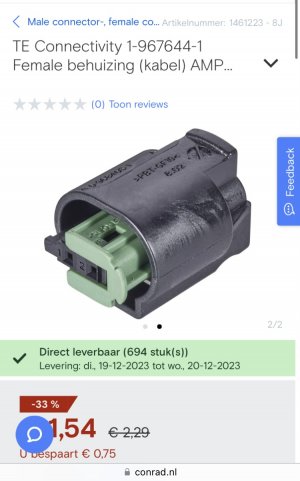
") I rigged up the control harness in the engine bay and the harness plug for the bypass module does not interfer with the rear carb and the bypass works as it should. I could feel the hot air from the heater core get cold as I turned the flow of coolant off, with the heat on. Itz gonna be brilliant on those muggy days!
I rigged up the control harness in the engine bay and the harness plug for the bypass module does not interfer with the rear carb and the bypass works as it should. I could feel the hot air from the heater core get cold as I turned the flow of coolant off, with the heat on. Itz gonna be brilliant on those muggy days!