It seems all of these died an early death. I've not found anything on how to fix these. I'm trying to troubleshoot what is wrong with mine but could use an extra one for parts and experimenting. Does anyone have one to sell, even if it doesn't work? TIA!
You are using an out of date browser. It may not display this or other websites correctly.
You should upgrade or use an alternative browser.
You should upgrade or use an alternative browser.
E3 Clocks --why do are they all dead?
- Thread starter Luis A.
- Start date
Removing, Disassembling and Repairing the Dash Clock
What's wrong with your clock? The problem with most of these old clocks is simple and easy to fix. The contacts that close to activate the winding solenoid become fouled, and the clock stops winding itself. Usually all that is needed to get your clock running is to clean the points. I used 200 grit sandpaper, but you may want to go to an electronics shop a buy some contact cleaner. If your clock is stopped with the contacts in the closed position, this is almost assuredly your problem. Clean the contacts, apply twelve volts DC to the clock and see if it springs to life. If you can see and hear the solenoid operating, your clock is probably fixed.
You may run into another problem after getting the solenoid operational. After not running for years, the clock mechanism may be a little stiff, and may not want to keep ticking for a full minute. What you need to do is help it along either by shaking the clock or by VERY GENTLY giving the WHEEL?? a little nudge when it stops. If you keep doing this, your clock should loosen up to the point where it will run for a whole minute. When that happens, your clock is fixed. You should keep it hooked up to the twelve volt source for a few days to make sure it's running right, and to see if it gains or looses time. There is a tiny adjustment screw on the back of the clock if it runs slow or fast.
I ran into a slightly different problem with another clock. The tiny printed circuit board associated with the solenoid had a problem. The printed circuit that carried the twelve volts to the solenoid had lifted up off the board and no longer contacted the twelve volt wire. I simply soldered the twelve volt wire straight to the separated printed circuit.
After your clock has been running fine for a few days or more, it's time to reinstall it. Push the plastic back into place and replace the tiny nuts. Reconnect the wires and secure the clock in the dash with the plastic nuts, remembering to replace the flimsy paper gasket.
I have resurrected two clocks in this fashion and both are ticking along flawlessly for over a year now.
Kevin Sweeney (CSR Newsletter XVI 1/2)
Removing the Clock from the Dash(Editor's Note: Back in Volume XV, we got you started on fixing your mechanical clock by revealing the secret of removing it from the dash and then we stopped. In consideration of the fact that many of you have been left so long with said instrument dangling from the dash by its wires and yet refrained from issuing death threats, and that we have had a number of new members, herewith follows the complete procedure.)
This is a process for removing, disassembling and actually repairing the mechanical VDO clocks found on the older coupes. The repair requires no special tools and no special technical or mechanical abilities.
Remove the under dash , driver's side vinyl (cardboard) trim panels. (Keep track of which screws go where. Some are different originally and some have been replaced with something else by a PO. Editor) Reach up under the dash and feel around for the two long (about 3 in) plastic nuts that hold the clock in place. The nuts are shaped like cigarettes. Remember that since they are facing you, you turn them what seems like clockwise to loosen. When they are loosened, a very slight rotation of the clock will free it up. If you can't get the clock free by loosening the nuts, remove them completely. It's a little tight under there, but some patient fiddling will get the clock past the metal dash supports. If you have very large hands and arms, you may want someone else do this for you. There is a flimsy paper gasket between the back of the instrument panel and the clock, so be careful not to damage it when you pull the clock. Pull (gently) the wires off the back of the clock, and label them or make a note of what they do. On mine red was 12v, brown was ground and another was for the clock's illumination.
DisassemblyThe metal back comes off the clock. There are three small nuts that hold it in place. Two are obvious, the third is covered with a green warranty protecting seal. Scrape the green stuff out and loosen that nut. The back can now be removed. Mine took a good deal of cajoling, but it will come off. Friction and about thirty years are the only thing holding it in place.
Clock TheoryThis is the fun part. The clock is not an electric clock at all, it is mechanical. The twelve volt connection powers a tiny solenoid which winds the clock once a minute. Those of you that have a functioning older clock can hear this operation if you sit quietly in your coupe with the engine turned off. Once a minute you will hear a soft "plunnnggg" (sic. Editor) sound coming from the direction of the clock. That ís the sound of the solenoid winding the clock's mainspring. The solenoid is actuated by a pair of contacts, (they look just like points) which come slowly together as the clock ticks. After closing, the solenoid is activated, which winds the mainspring, which, through a system of gears, opens the points. This process repeats itself once a minute. The mainspring is a low tension gizmo, unlike the ones found in a conventional mechanical watch or clock, because it only has to keep the clock running for a little over a minute.
Clock Fix (continued)What's wrong with your clock? The problem with most of these old clocks is simple and easy to fix. The contacts that close to activate the winding solenoid become fouled, and the clock stops winding itself. Usually all that is needed to get your clock running is to clean the points. I used 200 grit sandpaper, but you may want to go to an electronics shop a buy some contact cleaner. If your clock is stopped with the contacts in the closed position, this is almost assuredly your problem. Clean the contacts, apply twelve volts DC to the clock and see if it springs to life. If you can see and hear the solenoid operating, your clock is probably fixed.
You may run into another problem after getting the solenoid operational. After not running for years, the clock mechanism may be a little stiff, and may not want to keep ticking for a full minute. What you need to do is help it along either by shaking the clock or by VERY GENTLY giving the WHEEL?? a little nudge when it stops. If you keep doing this, your clock should loosen up to the point where it will run for a whole minute. When that happens, your clock is fixed. You should keep it hooked up to the twelve volt source for a few days to make sure it's running right, and to see if it gains or looses time. There is a tiny adjustment screw on the back of the clock if it runs slow or fast.
I ran into a slightly different problem with another clock. The tiny printed circuit board associated with the solenoid had a problem. The printed circuit that carried the twelve volts to the solenoid had lifted up off the board and no longer contacted the twelve volt wire. I simply soldered the twelve volt wire straight to the separated printed circuit.
After your clock has been running fine for a few days or more, it's time to reinstall it. Push the plastic back into place and replace the tiny nuts. Reconnect the wires and secure the clock in the dash with the plastic nuts, remembering to replace the flimsy paper gasket.
I have resurrected two clocks in this fashion and both are ticking along flawlessly for over a year now.
(Editor's Note: As a scientist, I observed a direct correlation between the mean ambient temperature in my garage and the rate at which my clock - which has never been removed - lost time. This thus makes it possible to track prevailing atmospheric conditions by proper calibration and careful (i.e.: anal retentive) record keeping. Conversely, those who really need therapy, can keep records of temperature and thus properly adjust the clock to an accurate representation of GMT.)
VDO Clock Repair
[Click on Photo]
Foreward by Wayne: Demick Boyden has written us a fine article on how to repair your VDO clock. The mechanisms from the various Porsche cars are very similar. Although Demick speaks specifically of the 914, the VDO clocks that are used within the other Porsche models all share a similar mechanism, and the similar repair problems. This article details the problems with the internal electrical solder connections that often fail. There are a few other problems with the clocks that cannot be repared without special parts, such as new pendulum springs. For clocks that need this additional repair, please contact Pelican Parts.

Figure 1:
Two Different Clock Mechanisms
VDO Clock Repair There are two types of clocks styles available in the 914 that I am aware of. Both look identical from the front, but are easily differentiated from the rear and have very different mechanisms inside. Both are shown in Figure 1. In the spirit of VW, I will refer to the clock on the left as Type I and the clock on the right as Type II. To the best of my knowledge, the Type I clock is the earlier model, and the Type II clock replaced it in 1973.
Comparing the two clocks, I like Type I much better. It is much easier to open up and you will have a much greater chance of successfully making repairs. Also, Type I has a way to externally adjust the speed at which the clock runs so you can dial it in to be quite accurate. Type II has a different clock mechanism which presumably eliminates the need for adjustment (since there is no external adjustment, although I believe there is an internal adjustment), but I have never had experience with an operating Type II clock so I cannot verify its accuracy.
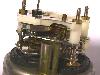
Figure 2:
Standard 3 Gauge Set on the 914
Type I The Type I clock has an easily removable rear cover. Three small nuts are all it takes to remove the rear cover (you may need to break the small plastic that goes around these nuts if the clock has never been opened up before). Inside you will find a series of gears and a coil and a couple of springs (Figure 2). There is a steel disk about ¾" in diameter near the rear end of the clock which has an electrical contact mounted under it. When this electrical contact is closed, current is sent to the coil which spins the steel disk around about ½ turn. This is how the clock is wound. The disk is spring loaded and will slowly over the course of about 3-4 minutes return to its original position - operating the clock as it goes around. When the contacts close again, the process starts all over again. For this reason, this clock only uses power for a fraction of a second every 3-4 minutes. You can turn the disk manually and see how this all works. The rest of clock works like a regular clock with all of the gears, etc.

Figure 3:
Standard 3 Gauge Set on the 914
This clock has a built-in fuse, which is what is normally the cause of this clock not working. Right next to the coil is a set of metal tabs which should be soldered together (Figure 3). If your clock is not working, chances are that these two tabs are no longer soldered. The process to repair it is simple: resolder the connection. To do this correctly, you need to use a low temperature solder (specification is solder with a fusing point of 120C or 248F). Where to find this? I don’t really know. I had some low temperature solder laying around which came in strips and was designed to be wrapped around a wire and then melted with a match. It never worked good like that, but it worked fine in this application (minus the match). I don’t know what the actual fusing point of this solder was though. Using regular solder is an option that will work fine, but someday your clock will really get fried because this fuse didn’t melt like it was supposed to and you will not be able to repair it. The choice is up to you. Also, when you solder the two tabs together, be sure that the top tab is pulled down (so it is spring loaded) to meet the other tab and then soldered. Don’t try to bridge the large gap because this spring loading is what helps to separate the tabs when the fuse melts. Note: The solder job shown is Figure 3 is NOT done correctly for exactly this reason (big blob of solder bridging the gap) Well, that’s about it! Put the rear cover back on and plug it in. Adjustment of the clock speed is made by the small slotted screw which protrudes through the rear cover. Counter-clockwise goes faster. Best that I can tell, each 1/8 of a turn affects the clock by about 5 minutes per day.
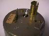
Figure 4:
Standard 3 Gauge Set on the 914
Figure 5:
Standard 3 Gauge Set on the 914

Figure 6:
Standard 3 Gauge Set on the 914

Figure 7:
Standard 3 Gauge Set on the 914
Type II Getting inside the Type II clock is a bit more difficult. Just like most all of the other 914 instrumentation, it involves using a sharp object (small screwdriver, chisel, etc) and carefully prying around the outside of the outer face ring. This part is a real pain. You will have to pry the formed flange up for at least ½ of the way around the clock, and then remove the clock ring and glass from the rest of the canister. Now it is time to remove the guts of the clock from the canister: remove the 3 screws from the rear surface of the clock and unsolder the ground connection (Figure 4). The guts of the clock should now slide out (Figure 5).
Once open, you will notice that the inside looks quite different from the Type I clock. This clock is run by an electric motor rather than a spring loaded disk wound by a coil. The most common failure with this type of clock is a damaged gear. In my case, it was a gear whose support shaft had broken. In order to fix this shaft, I wanted to separate the PCB portion of the clock from the gear portion (shown separated in Figure 6). This is possible to do given the following: Remove the obvious screw which holds the PCB on, and unsolder the two posts which are arrowed in Figure 7. These two posts are how the electrical connection is made to the electric motor. If you do not unsolder these posts, the PCB is still very easy to remove, but your clock will never work again. The posts will come out with the PCB, but the very fine wires which go into the motor will break and there is no way to re-connect them (I know, I’ve tried - that’s why the motor in Figure 7 is partially cut open). With the PCB removed, you can get access to do the gear repair. In my clock, I did the gear repair very carefully with epoxy, and then found out on re-assembly about the broken wires - but I am confident that the repairs would have worked had I not broken the wires.
Re-assembly is just the reverse of this process. Test the clock before putting it completely back together (that face ring is really a pain - you don’t want to do it twice). Also, note in Figure 6 that there is an adjustment pot mounted to the PCB. I believe that this pot is the clock speed adjustment and it is not accessible except by clock dis-assembly.
VDO Clock Repair
[Click on Photo]
Foreward by Wayne: Demick Boyden has written us a fine article on how to repair your VDO clock. The mechanisms from the various Porsche cars are very similar. Although Demick speaks specifically of the 914, the VDO clocks that are used within the other Porsche models all share a similar mechanism, and the similar repair problems. This article details the problems with the internal electrical solder connections that often fail. There are a few other problems with the clocks that cannot be repared without special parts, such as new pendulum springs. For clocks that need this additional repair, please contact Pelican Parts.

Figure 1:
Two Different Clock Mechanisms
VDO Clock Repair There are two types of clocks styles available in the 914 that I am aware of. Both look identical from the front, but are easily differentiated from the rear and have very different mechanisms inside. Both are shown in Figure 1. In the spirit of VW, I will refer to the clock on the left as Type I and the clock on the right as Type II. To the best of my knowledge, the Type I clock is the earlier model, and the Type II clock replaced it in 1973.
Comparing the two clocks, I like Type I much better. It is much easier to open up and you will have a much greater chance of successfully making repairs. Also, Type I has a way to externally adjust the speed at which the clock runs so you can dial it in to be quite accurate. Type II has a different clock mechanism which presumably eliminates the need for adjustment (since there is no external adjustment, although I believe there is an internal adjustment), but I have never had experience with an operating Type II clock so I cannot verify its accuracy.

Figure 2:
Standard 3 Gauge Set on the 914
Type I The Type I clock has an easily removable rear cover. Three small nuts are all it takes to remove the rear cover (you may need to break the small plastic that goes around these nuts if the clock has never been opened up before). Inside you will find a series of gears and a coil and a couple of springs (Figure 2). There is a steel disk about ¾" in diameter near the rear end of the clock which has an electrical contact mounted under it. When this electrical contact is closed, current is sent to the coil which spins the steel disk around about ½ turn. This is how the clock is wound. The disk is spring loaded and will slowly over the course of about 3-4 minutes return to its original position - operating the clock as it goes around. When the contacts close again, the process starts all over again. For this reason, this clock only uses power for a fraction of a second every 3-4 minutes. You can turn the disk manually and see how this all works. The rest of clock works like a regular clock with all of the gears, etc.

Figure 3:
Standard 3 Gauge Set on the 914
This clock has a built-in fuse, which is what is normally the cause of this clock not working. Right next to the coil is a set of metal tabs which should be soldered together (Figure 3). If your clock is not working, chances are that these two tabs are no longer soldered. The process to repair it is simple: resolder the connection. To do this correctly, you need to use a low temperature solder (specification is solder with a fusing point of 120C or 248F). Where to find this? I don’t really know. I had some low temperature solder laying around which came in strips and was designed to be wrapped around a wire and then melted with a match. It never worked good like that, but it worked fine in this application (minus the match). I don’t know what the actual fusing point of this solder was though. Using regular solder is an option that will work fine, but someday your clock will really get fried because this fuse didn’t melt like it was supposed to and you will not be able to repair it. The choice is up to you. Also, when you solder the two tabs together, be sure that the top tab is pulled down (so it is spring loaded) to meet the other tab and then soldered. Don’t try to bridge the large gap because this spring loading is what helps to separate the tabs when the fuse melts. Note: The solder job shown is Figure 3 is NOT done correctly for exactly this reason (big blob of solder bridging the gap) Well, that’s about it! Put the rear cover back on and plug it in. Adjustment of the clock speed is made by the small slotted screw which protrudes through the rear cover. Counter-clockwise goes faster. Best that I can tell, each 1/8 of a turn affects the clock by about 5 minutes per day.

Figure 4:
Standard 3 Gauge Set on the 914

Figure 5:
Standard 3 Gauge Set on the 914

Figure 6:
Standard 3 Gauge Set on the 914

Figure 7:
Standard 3 Gauge Set on the 914
Type II Getting inside the Type II clock is a bit more difficult. Just like most all of the other 914 instrumentation, it involves using a sharp object (small screwdriver, chisel, etc) and carefully prying around the outside of the outer face ring. This part is a real pain. You will have to pry the formed flange up for at least ½ of the way around the clock, and then remove the clock ring and glass from the rest of the canister. Now it is time to remove the guts of the clock from the canister: remove the 3 screws from the rear surface of the clock and unsolder the ground connection (Figure 4). The guts of the clock should now slide out (Figure 5).
Once open, you will notice that the inside looks quite different from the Type I clock. This clock is run by an electric motor rather than a spring loaded disk wound by a coil. The most common failure with this type of clock is a damaged gear. In my case, it was a gear whose support shaft had broken. In order to fix this shaft, I wanted to separate the PCB portion of the clock from the gear portion (shown separated in Figure 6). This is possible to do given the following: Remove the obvious screw which holds the PCB on, and unsolder the two posts which are arrowed in Figure 7. These two posts are how the electrical connection is made to the electric motor. If you do not unsolder these posts, the PCB is still very easy to remove, but your clock will never work again. The posts will come out with the PCB, but the very fine wires which go into the motor will break and there is no way to re-connect them (I know, I’ve tried - that’s why the motor in Figure 7 is partially cut open). With the PCB removed, you can get access to do the gear repair. In my clock, I did the gear repair very carefully with epoxy, and then found out on re-assembly about the broken wires - but I am confident that the repairs would have worked had I not broken the wires.
Re-assembly is just the reverse of this process. Test the clock before putting it completely back together (that face ring is really a pain - you don’t want to do it twice). Also, note in Figure 6 that there is an adjustment pot mounted to the PCB. I believe that this pot is the clock speed adjustment and it is not accessible except by clock dis-assembly.
blumax
(deceased)
E-3 clock(s) available
I have a couple that I bought--they were from a parted 1976 3.0 Si--don't know if it/they work as I have since sold my Bavaria--but still have them and a bunch of other very good to excellent E-3 parts that I will post for sale in the next day or two.
Give me a call if you are interested in the clocks or have other E-3 needs.
Murray
949-642-2150
Tierfreund
Well-Known Member
I´m on my third E3 and all three had working clocks.... go figure...
Thanks so much for posting that link Steve. I hadn't thought of that great ally of the vintage car owner: commonality of OEM suppliers. It's saved me more than once with my French cars.
Sure enough, a search of the web revealed the early Kienzle mechanism clock, called Type 1 in the piece you posted, is found on Mercedes, Porsche and BMW vehicles up to somewhere in the early 70's when the quartz oscillator clocks, labeled "Quarz-Zeit" on the face, appeared. My '66 1800 has a Kienzle drive and the '73 coupe and '76 Si both have a quartz mechanism.
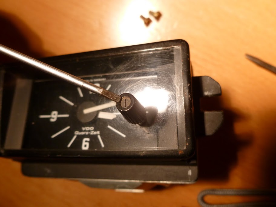
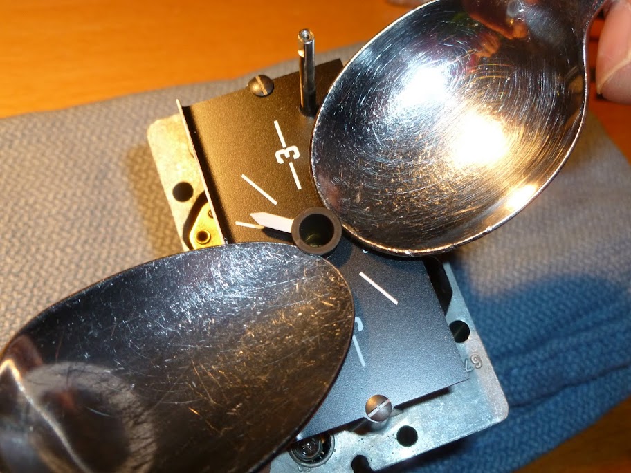
It's very simple to disassemble the clock to get to the point where you have to remove the hands in order to remove the face, which is held by two small screws. In order to remove them without the risk of bending you need to apply equal lifting force from both sides. Best tool to use is a pair of spoons. Small, espresso spoons would have worked better but this is a German car so strudel spoons were called into action. This technique works equally well to remove VDO speedo, tach and other gauge needles, which are much tougher to remove without damage.
A very tiny screw holds the time setting knob:
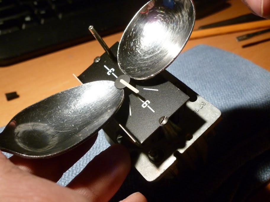
...and upon removal of the face, this is the view:

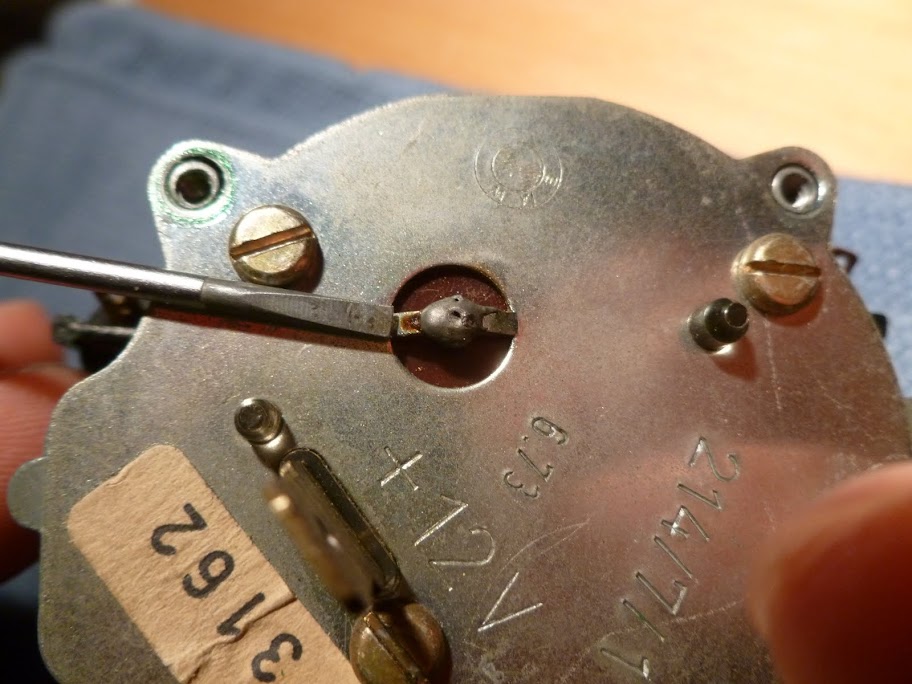
Now, turning to the back, there are 4 screws on the corners holding the back plate to the clock (two removed screws visible in this photo) as well as the ground connection to the back plate, emerging from the circuit board that lurks beneath:
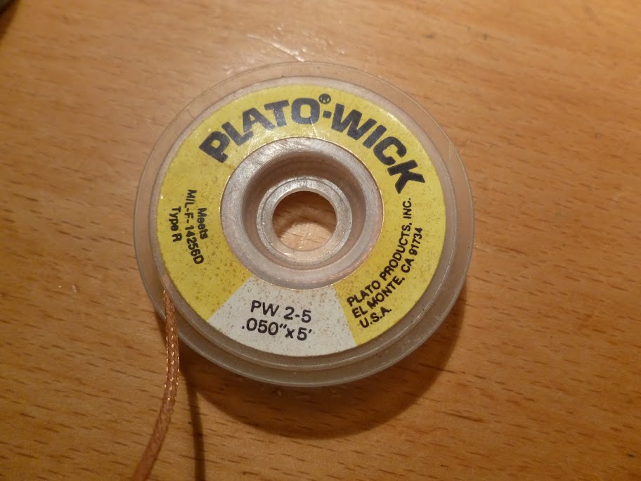
This is where solder wick comes in real handy:
I used a 25 W soldering iron, 30 or more would have been much quicker. After wicking away, or otherwise removing as much solder as you can, the three remaining screws can be removed...
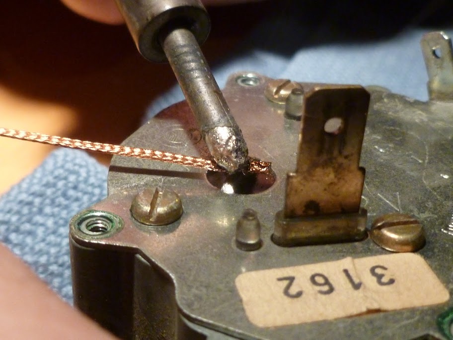
...but you might find out that the minute amount of solder left in place will still be holding the back down. So just apply the soldering iron at the same time you are pulling the back away and it will pop off. This pulling-while-heating might have worked from the start without using any solder wick but you will see later where you might really need the solder wick.
It's off!

Small phenolic disk surrounds the ground post laying on top of a foam separator. Remove both and you have a clear view of the back of the circuit board.

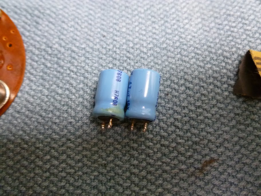
The circuit board contains two electrolytic capacitors that are very likely the problem if the clock isn't running at all. They are rated at 16V, which leaves little safety margin. Radio Shack quality caps are at least 35V nowadays. Both caps in my clock were 47 uF (microfarads) and I happened to have two in my junk drawer (clean living!:grin") but you can find them at Radio Shack. If you look closely you might even see some evidence of leakage from the old caps. Just desolder and replace the capacitors with new ones and you should be done. Here are my old caps:
but you can find them at Radio Shack. If you look closely you might even see some evidence of leakage from the old caps. Just desolder and replace the capacitors with new ones and you should be done. Here are my old caps:
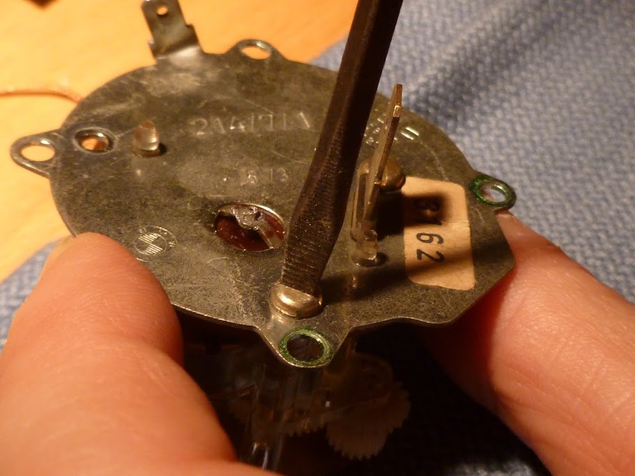
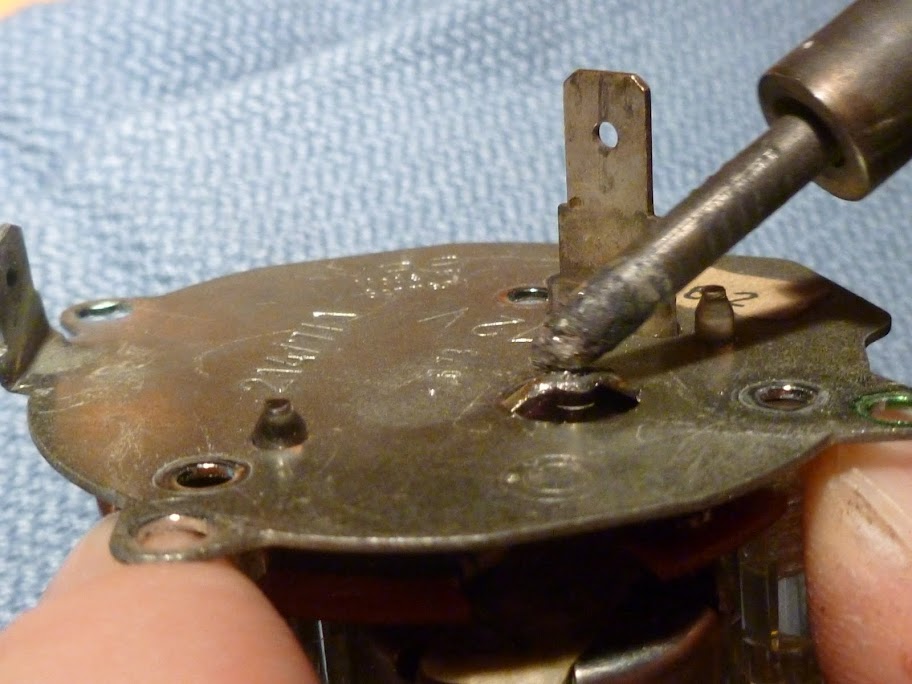
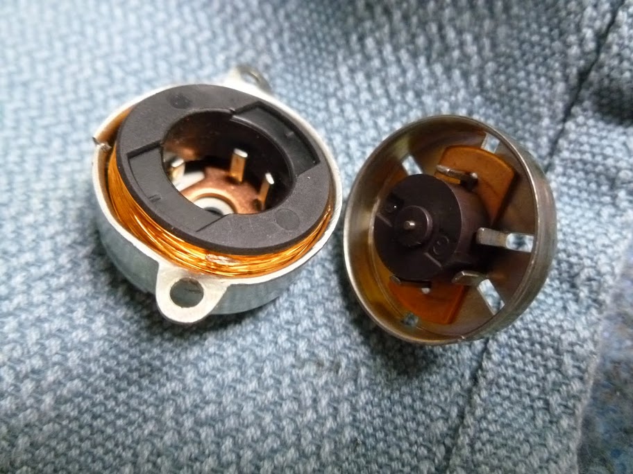
For extra credit, I wanted to remove the circuit board off the clock gearing and that's when I got into trouble. Besides the obvious screw on the PCB, the electric motor terminal pins are the last thing holding the board to the mechanism, they are the two solder points identified here:
From below, you can see both pins and the very thin wire that emerges from the motor winding and wraps around the pins:
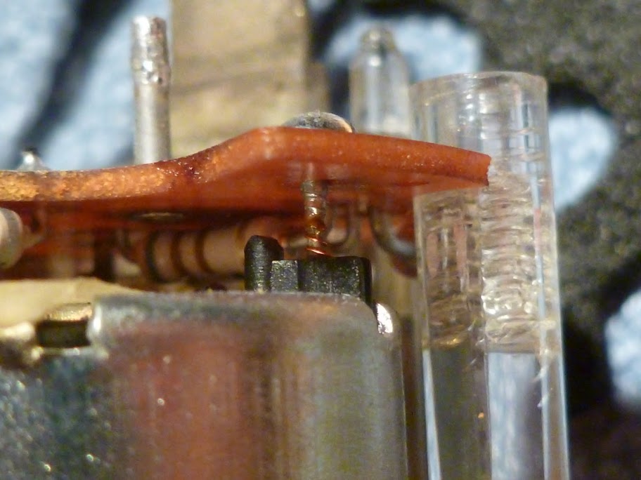
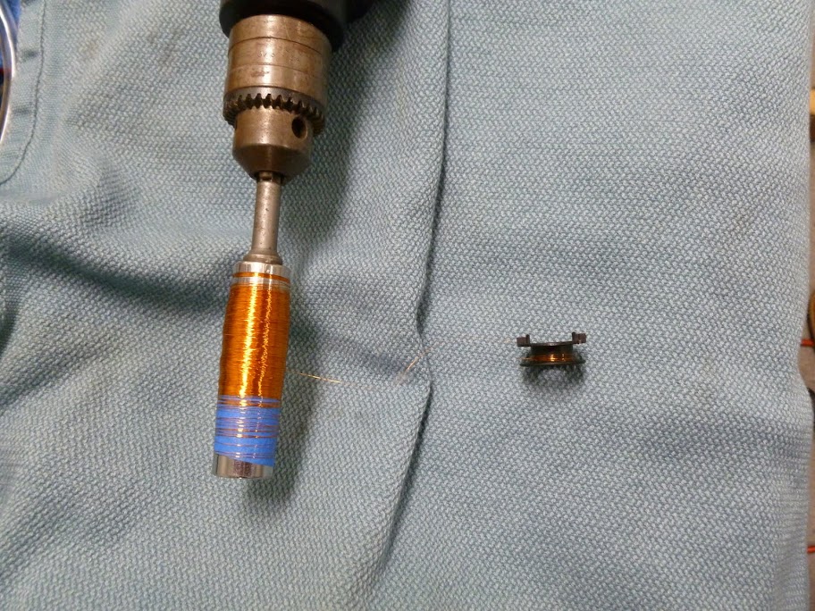
If you try to just apply the soldering iron to those solder joints and pull as you heat, odds are you will pull off the winding wire and snap it off the motor. Use the wick. I didn't at first and one of the wires snapped off and it was the one that is at the inner, or beginning, of the winding core. The only way of getting at it and reattaching it to the terminal pin was to crack open the motor, unwind the angel hair wire onto another temporary spool and then rewind it back onto the core. This wire is incredibly thin, 0.08 mm, to be exact.
So... If you are reading this post, and it is the year 2041 and all E3 clocks have been extinct for years, you also might want to attempt this repair...:roll: For posterity, here is the abridged photo essay:
Before you attempt to solder the wire, don't forget to sand it with 800 grit or smaller since it's enamel-coated.
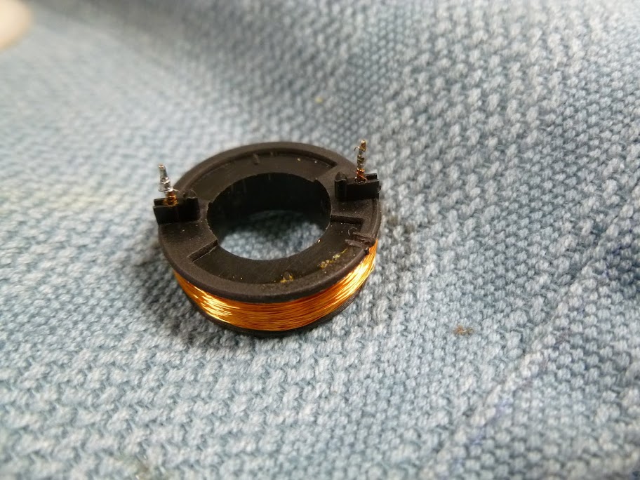
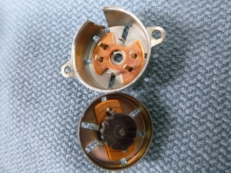
Motor back in place. At the clock factory, it is riveted with very small rivets to the plastic gearing base, but something as 'rednecky' as twisted up teflon tape (strong and with a little bit of stretch) works wonderfully to secure it back in place. Gore dental floss would have been as good, or better.

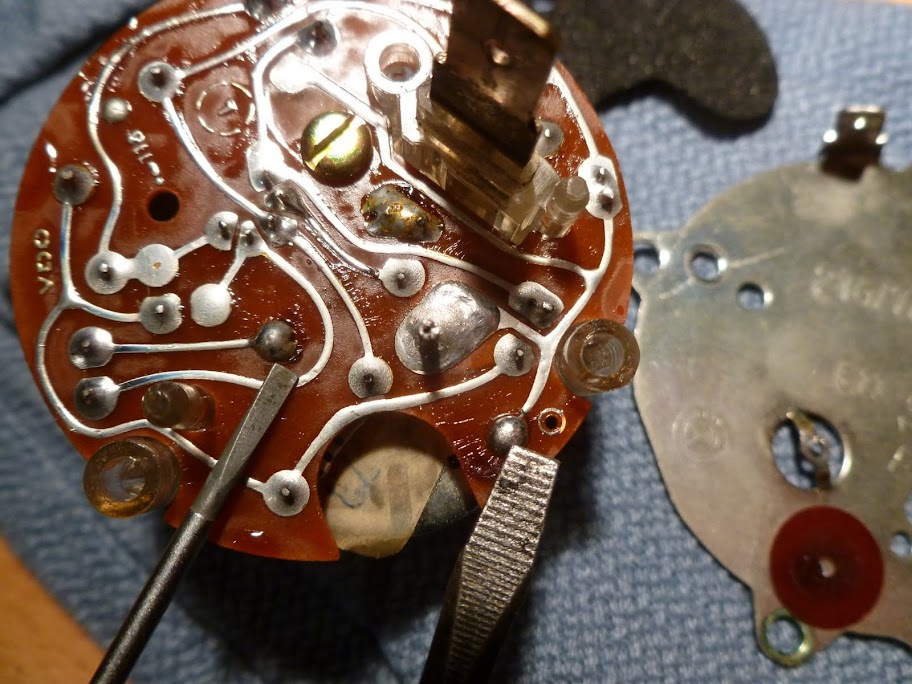
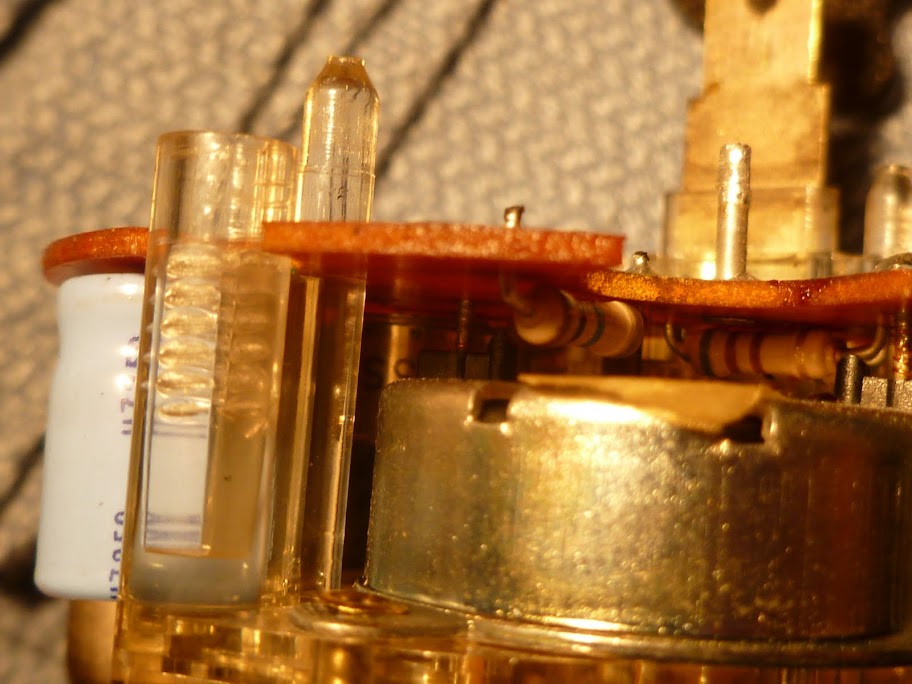
My clock has been running with under a minute a week discrepancy without any adjustment, but there is trimmer cap on the circuit board, it's the component on the left with the screw on top. The new caps are seen on this photo.

And finally, it works!! Current consumption is around 8-10 milliamps, BTW.
http://www.youtube.com/watch?v=h6VOsVVs2mo
Sure enough, a search of the web revealed the early Kienzle mechanism clock, called Type 1 in the piece you posted, is found on Mercedes, Porsche and BMW vehicles up to somewhere in the early 70's when the quartz oscillator clocks, labeled "Quarz-Zeit" on the face, appeared. My '66 1800 has a Kienzle drive and the '73 coupe and '76 Si both have a quartz mechanism.
It's very simple to disassemble the clock to get to the point where you have to remove the hands in order to remove the face, which is held by two small screws. In order to remove them without the risk of bending you need to apply equal lifting force from both sides. Best tool to use is a pair of spoons. Small, espresso spoons would have worked better but this is a German car so strudel spoons were called into action. This technique works equally well to remove VDO speedo, tach and other gauge needles, which are much tougher to remove without damage.
A very tiny screw holds the time setting knob:
...and upon removal of the face, this is the view:
Now, turning to the back, there are 4 screws on the corners holding the back plate to the clock (two removed screws visible in this photo) as well as the ground connection to the back plate, emerging from the circuit board that lurks beneath:
This is where solder wick comes in real handy:
I used a 25 W soldering iron, 30 or more would have been much quicker. After wicking away, or otherwise removing as much solder as you can, the three remaining screws can be removed...
...but you might find out that the minute amount of solder left in place will still be holding the back down. So just apply the soldering iron at the same time you are pulling the back away and it will pop off. This pulling-while-heating might have worked from the start without using any solder wick but you will see later where you might really need the solder wick.
It's off!
Small phenolic disk surrounds the ground post laying on top of a foam separator. Remove both and you have a clear view of the back of the circuit board.
The circuit board contains two electrolytic capacitors that are very likely the problem if the clock isn't running at all. They are rated at 16V, which leaves little safety margin. Radio Shack quality caps are at least 35V nowadays. Both caps in my clock were 47 uF (microfarads) and I happened to have two in my junk drawer (clean living!:grin
but you can find them at Radio Shack. If you look closely you might even see some evidence of leakage from the old caps. Just desolder and replace the capacitors with new ones and you should be done. Here are my old caps:
For extra credit, I wanted to remove the circuit board off the clock gearing and that's when I got into trouble. Besides the obvious screw on the PCB, the electric motor terminal pins are the last thing holding the board to the mechanism, they are the two solder points identified here:
From below, you can see both pins and the very thin wire that emerges from the motor winding and wraps around the pins:
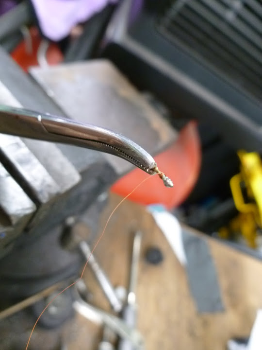
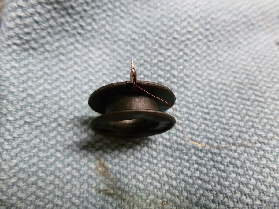
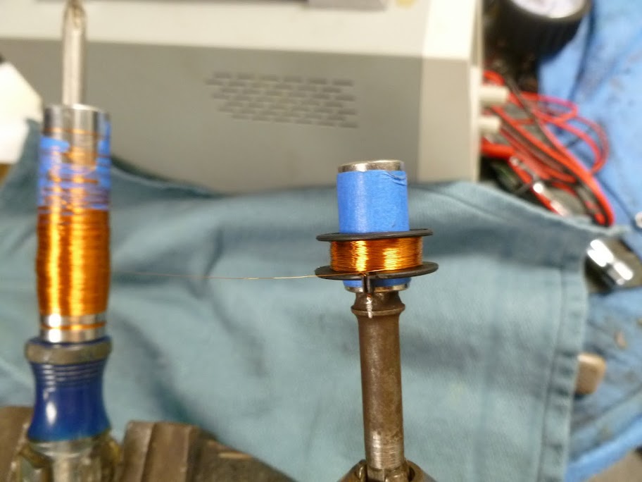
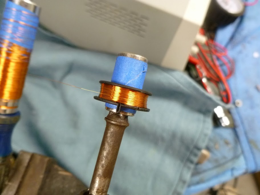
If you try to just apply the soldering iron to those solder joints and pull as you heat, odds are you will pull off the winding wire and snap it off the motor. Use the wick. I didn't at first and one of the wires snapped off and it was the one that is at the inner, or beginning, of the winding core. The only way of getting at it and reattaching it to the terminal pin was to crack open the motor, unwind the angel hair wire onto another temporary spool and then rewind it back onto the core. This wire is incredibly thin, 0.08 mm, to be exact.
So... If you are reading this post, and it is the year 2041 and all E3 clocks have been extinct for years, you also might want to attempt this repair...:roll: For posterity, here is the abridged photo essay:
Before you attempt to solder the wire, don't forget to sand it with 800 grit or smaller since it's enamel-coated.
Motor back in place. At the clock factory, it is riveted with very small rivets to the plastic gearing base, but something as 'rednecky' as twisted up teflon tape (strong and with a little bit of stretch) works wonderfully to secure it back in place. Gore dental floss would have been as good, or better.
My clock has been running with under a minute a week discrepancy without any adjustment, but there is trimmer cap on the circuit board, it's the component on the left with the screw on top. The new caps are seen on this photo.
And finally, it works!! Current consumption is around 8-10 milliamps, BTW.
http://www.youtube.com/watch?v=h6VOsVVs2mo
Wow nice work, you are giving DeQuincey a run for his money!