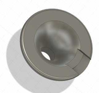
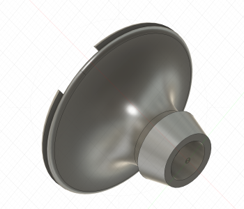
E9 A/C Condensate Drain

i would make your lock easier to push in from the top without being so pronounced of a ring. here's an idea based on the dimensions on my car - the hole is 10mm (i'm thinking of making it a little bigger - 12mm). the dimension from the top of the tranny tunnel to the top of the mounting plate is 13mm. the opening in the top of the mounting plate is 30mm.
 

Attachments

i would make your lock easier to push in from the top without being so pronounced of a ring. here's an idea based on the dimensions on my car - the hole is 10mm (i'm thinking of making it a little bigger - 12mm). the dimension from the top of the tranny tunnel to the top of the mounting plate is 13mm. the opening in the top of the mounting plate is 30mm.
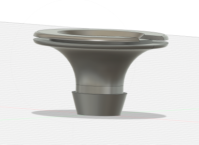
Does your evaporator box have a feed hose or pipe on the bottom? Mine does, but it is 3.0 CS.

If it does, then I think we should make some accommodation for that in the drain funnel.
 
Here's the 3D model. I added a barb on the bottom to seal the tunnel. To assemble this you would install the upper grommet into the mounting plate, and then press the plate and the lower part of the grommet into the 12 mm hole. The diameter of the bottom of the barb is 11 mm, and the outside diameter of the tube just above the barb is 12 mm, so it will locate and snap in as you press down. All other dimensions are per your drawing.

PM me your email and I'll send you the .stl file
 

Attachments

  • Screenshot 2026-07-06 at 5.12.51 PM.png
    Screenshot 2026-07-06 at 5.12.51 PM.png
    1.3 MB · Views: 10
  • Screenshot 2026-07-06 at 5.13.10 PM.png
    Screenshot 2026-07-06 at 5.13.10 PM.png
    839.5 KB · Views: 7
  • Screenshot 2026-07-06 at 5.13.25 PM.png
    Screenshot 2026-07-06 at 5.13.25 PM.png
    1 MB · Views: 11
I like the way you guys are thinking. I've got most of what I need to add AC to my coupe, but the drain is a crucial part I'd not resolved yet. I don't think it's too much of a problem to have condensate drip down over your transmission. I'd toyed with the idea of having a hose that directs the flow around the transmission, but the space is limited and bends might encourage blockage.
Speaking of blockage, I wonder if it's possible to get the proposed drain you're working on made with a material that is resistant to mold growth. This could offset the inability to access the installed drain from above or below to clear blockages by reducing their formation.
Just a thought.
 
Here's the 3D model. I added a barb on the bottom to seal the tunnel. To assemble this you would install the upper grommet into the mounting plate, and then press the plate and the lower part of the grommet into the 12 mm hole. The diameter of the bottom of the barb is 11 mm, and the outside diameter of the tube just above the barb is 12 mm, so it will locate and snap in as you press down. All other dimensions are per your drawing.

PM me your email and I'll send you the .stl file
Scott, not sure the top grommet lock is thick enough. the mounting plate is 2mm thick.
my evaporator has a 10mm drop ... but its only about 1/4" long. so this should drop into the little drain funnel. i may try stretching some kind of thin hose over the drain on the evaporator to make sure everything goes into the funnel.
 
Scott, not sure the top grommet lock is thick enough. the mounting plate is 2mm thick.
my evaporator has a 10mm drop ... but its only about 1/4" long. so this should drop into the little drain funnel. i may try stretching some kind of thin hose over the drain on the evaporator to make sure everything goes into the funnel.
OK. Hold off on the file I sent. I'll enlarge the grommet groove
 
Couple thoughts on the design as well: Rather than a barb at the bottom or a ring that sticks out, the piece I used had a indented slot/grover. This would stop it from getting pushed down accidentally either as you put it in, or as the evap box comes down. Having it tapered like the bard would still be needed. If you go this way, giving that indented locating ring a bit of extra hight would be good as the mounting plate may sit a little higher or lower car to car (+/- 1 mm or so.). If the whole thing is very flexible, this will not matter as much.
 
Couple thoughts on the design as well: Rather than a barb at the bottom or a ring that sticks out, the piece I used had a indented slot/grover. This would stop it from getting pushed down accidentally either as you put it in, or as the evap box comes down. Having it tapered like the bard would still be needed. If you go this way, giving that indented locating ring a bit of extra hight would be good as the mounting plate may sit a little higher or lower car to car (+/- 1 mm or so.). If the whole thing is very flexible, this will not matter as much.
Not sure how flexible the elastomer actually is. But I agree if it is pretty squishy, then making the top ring taller would assure a solid seal.

I am not super clear on the "indented slot" suggestion.

My original design had two grooves, one for the trans tunnel, and one for the mounting plate, but we thought it might be too difficult to seat both grooves. So are you suggesting making the barb smaller so it is easier to insert, but adding a stop above, so it doesn;t get pushed too far in? That seems like an interesting idea. Here's a version like that.
Screenshot 2026-07-09 at 8.39.17 AM.png


Screenshot 2026-07-09 at 8.39.41 AM.png
 
Last edited:
remember, it isn't going anywhere as its locked into the mounting bracket which is screwed to the tranny tunnel. i have a few on order for a test + we will find out in a couple of weeks when the first pieces arrive. one thing that may change the length is the thickness of any insulation on the floor and how much the carpet holds it up.
 
Here's another thought. Unclear why the funnel needs to be super secured top and bottom. It certainly should be sealed to the tunnel, but ultimately it just needs to be positioned under the evaporator. Here is a design that basically pushes into he tunnel and locks, but just sits onthe mounting plate. Seems much easier to install.

Screenshot 2026-07-09 at 8.52.28 AM.png


Screenshot 2026-07-09 at 8.52.48 AM.png
 
i prefer the lock in the removable plate rather than trying to manipulate a lock after pushing it thru the plate. i think it would be fine to just have a tapered bottom with no lock and the physical lock at the top. once you put it on the plate, then position the drain into the hole and lock the plate into position ... it ain't going anywhere.
 
i prefer the lock in the removable plate rather than trying to manipulate a lock after pushing it thru the plate. i think it would be fine to just have a tapered bottom with no lock and the physical lock at the top. once you put it on the plate, then position the drain into the hole and lock the plate into position ... it ain't going anywhere.
Yeah, probably true.

What are your thoughts onthe dimensions? I can't recall how the plate is attached to the tunnel. Is the padding/insulation/carpet cut away for the plate feet to attach, or is it all just attached on top of that stuff? (Which would seem to be a bit flaky)
 
Scott, theoretically the plate mounts to the top of the tranny tunnel and the insulation / carpet is cut away. that is how i will be installing it as i don't want to make anything above tighter than it needs to be
 
i prefer the lock in the removable plate rather than trying to manipulate a lock after pushing it thru the plate. i think it would be fine to just have a tapered bottom with no lock and the physical lock at the top. once you put it on the plate, then position the drain into the hole and lock the plate into position ... it ain't going anywhere.
I don't think we can totally disregard the capillary action of water. If the bottom of the spout ends close to the transmission tunnel, which could happen if there is a lot of sound damping and carpet under the plate, then the water could move up a bit and reenter the cabin and travel under the sound insulation and possibly wet the carpet.
Extending the spout so it protrudes maybe 10mm, or even more to allow for trimming if there isn't any sound insulation, would cover more installation variables.
Having it locked to the plate makes sense both for ease of installation of the evaporator and long term durability.
 
The image in post #14 in this thread shows installation of the bracket on top of the carpet for a retro fit of the AC. Of course adding aftermarket sound insulation could reduce clearances to the point of making the install very difficult.
 
right now, the dimension from the top of the tranny tunnel to the bottom of the drain is about 5 mm. perhaps a few more would make sense. as long as you have a physical lip, you will create a 'drip stop'. i don't see water going up 5+ mm thru a tight gap between rubber + metal. i could see a total of 10mm, but i don't think you want to push it down more as the tranny isn't that far away - i will see if i can measure the distance.

The image in post #14 in this thread shows installation of the bracket on top of the carpet for a retro fit of the AC. Of course adding aftermarket sound insulation could reduce clearances to the point of making the install very difficult.
not really, the grommet is sitting on the carpet but the hole + bracket mount is exposed tranny tunnel.
 
I spent a couple of hours today over at Don's shop. One of the topics we discussed was this one. He had two cars that we used as test cases. One was an AC retrofit car, and the other was an AC original car.

I recognize that technically all of the AC cars were retrofit, just some at the dealer prior to sale, and others in the field. So there is going to be some variability in the setup. What I learned today was this:

  • The evaporator mounts firmly to the mounting plate, which has feet that attach it firmly to the transmission tunnel.
  • The funnel attaches to the mounting plate using the large grommet-like end. The padding and carpet are all cut away, so there is no significant variation in separation between the tunnel and the routing plate.
  • The hole in the tunnel on an original AC car is actually about the same size as the hole in the mounting plate (30mm). The funnel piece does not contact the tunnel at all.
  • There is a SECOND seal that seals the mounting plate to the trans tunnel (more on this below)
  • The funnel extends down at least to the level of the tunnel, possibly past it, as @rsporsche notes, about 5 mm.
  • The evaporator box has a small pipe extension on the bottom that engages with and seals to the funnel.
Here is a diagram showing the setup.
Screenshot 2026-07-09 at 1.48.45 PM.png


The drain tube in the evaporator box is 15 mm dia, and 6.5 mm long.
The top of the mounting plate sits 21 mm above the top of the tunnel.

Don says the big foam "donut" is made from some fairly stiff closed cell foam. On one car we looked at it was crumbling from age, heat, and oily gunk. This is part #2 in the diagram below (64511352344). Oddly the "funnel" is shown here as two parts 16 (64511352063), and 17 (64511352205).
Screenshot 2026-07-09 at 1.56.29 PM.png
 
Last edited:
Back
Top