Fuel Pump Harness Routing – Need Help Tracing the Path to the Trunk (CSi Restoration)

LEO

Active Member
Messages
48
Reaction score
11
Location
BOGOTA COLOMBIA
Well, as I’ve mentioned before, I’m trying to bring my White Shark CSi back to life — it’s been completely disassembled since 2019. Right now, we’re knee-deep in the restoration of the wiring harness, and I’ve run into something strange.

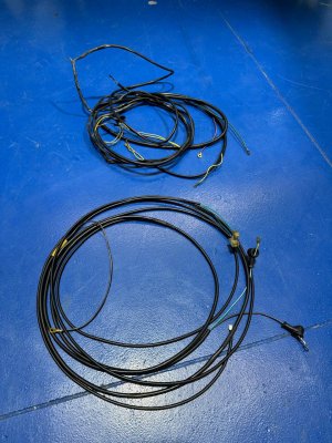
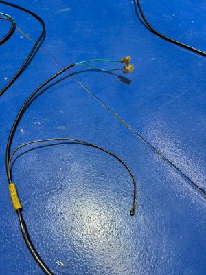
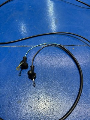
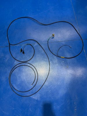
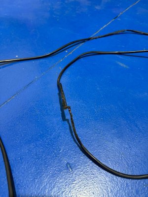
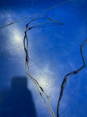
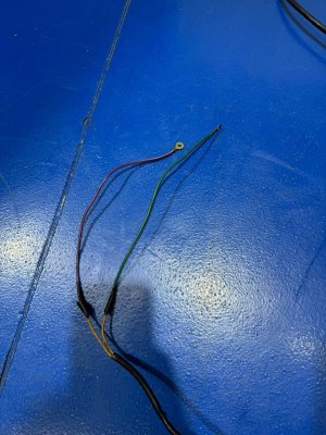
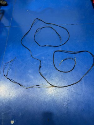
I found a section of the harness with very long, burned wires that belong to the fuel pump circuit. Oddly enough, all of these wires are yellow, but according to the documentation I’ve managed to find, they should be green with a white stripe, and of course brown for ground. We’ve already corrected that part, but now we’re breaking our heads trying to figure out how to route this harness properly.

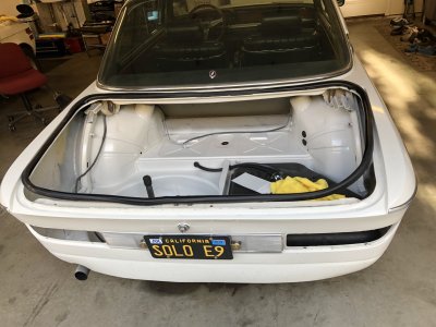
We know the fuel pump relay sits under the seat, and that the power to the relay comes from a male connector under the rear “turtle” panel, but I’m not sure how it gets to the trunk — or through which hole it passes.

If anyone has photos or diagrams to help me visualize this, I’d be deeply grateful from the bottom of my heart.

Cheers,
 

Attachments

  • WhatsApp Image 2025-10-28 at 07.59.05.jpeg
    WhatsApp Image 2025-10-28 at 07.59.05.jpeg
    234.6 KB · Views: 21
  • WhatsApp Image 2025-10-28 at 07.59.04 (7).jpeg
    WhatsApp Image 2025-10-28 at 07.59.04 (7).jpeg
    236 KB · Views: 15
  • WhatsApp Image 2025-10-28 at 07.59.04 (6).jpeg
    WhatsApp Image 2025-10-28 at 07.59.04 (6).jpeg
    218.6 KB · Views: 13
  • WhatsApp Image 2025-10-28 at 07.59.04 (5).jpeg
    WhatsApp Image 2025-10-28 at 07.59.04 (5).jpeg
    211 KB · Views: 13
  • WhatsApp Image 2025-10-28 at 07.59.04 (4).jpeg
    WhatsApp Image 2025-10-28 at 07.59.04 (4).jpeg
    212.8 KB · Views: 11
  • WhatsApp Image 2025-10-28 at 07.59.04 (3).jpeg
    WhatsApp Image 2025-10-28 at 07.59.04 (3).jpeg
    146.7 KB · Views: 11
  • WhatsApp Image 2025-10-28 at 07.59.04 (2).jpeg
    WhatsApp Image 2025-10-28 at 07.59.04 (2).jpeg
    181.3 KB · Views: 11
  • WhatsApp Image 2025-10-28 at 07.59.04 (1).jpeg
    WhatsApp Image 2025-10-28 at 07.59.04 (1).jpeg
    190.1 KB · Views: 8
  • WhatsApp Image 2025-10-28 at 07.59.04.jpeg
    WhatsApp Image 2025-10-28 at 07.59.04.jpeg
    184.7 KB · Views: 10
I can't help with the routing because I have a different car (CS) , but I am wondering about your splices. First off can you be certain that you got the brown wire on the grounded yellow wire? Second, how did you make the electrical connection? Solder connections out in the wild may crack from temperature variation and vibration. generally splices are done using crimp connectors, or just spade connectors if it is one wire. Third, it looks like you just wrapped the splices with black electrical tape. That stuff will dry out and unravel at the splice over time. I'd at a minimum replace the tape with a heat shrink sleeve (will need to cut and re-joint the wires to do this.

While it s not a perfect solution, I have used Ancor marine crimp splices in my boat with good success (in a very damp environment). These come with a heat shrink sleeve over the joint. So you insert the wires, crimp and then heat the sleeve. The heat shrinks the sleeve and also activates a sealing goo that melts around the wires. So the result is pretty much water and vibration proof. See pic below.

There are also soldered splices that operate onthe same principle (with solder instead of a crimp). In those the het from the heat gun melts the older and also shrinks the tube and activates the goo. Pic below.
 

Attachments

  • Screenshot 2025-10-28 at 7.09.00 AM.png
    Screenshot 2025-10-28 at 7.09.00 AM.png
    446.1 KB · Views: 8
  • Screenshot 2025-10-28 at 7.09.51 AM.png
    Screenshot 2025-10-28 at 7.09.51 AM.png
    215.2 KB · Views: 18
  • Like
Reactions: LEO
I can't help with the routing because I have a different car (CS) , but I am wondering about your splices. First off can you be certain that you got the brown wire on the grounded yellow wire? Second, how did you make the electrical connection? Solder connections out in the wild may crack from temperature variation and vibration. generally splices are done using crimp connectors, or just spade connectors if it is one wire. Third, it looks like you just wrapped the splices with black electrical tape. That stuff will dry out and unravel at the splice over time. I'd at a minimum replace the tape with a heat shrink sleeve (will need to cut and re-joint the wires to do this.

While it s not a perfect solution, I have used Ancor marine crimp splices in my boat with good success (in a very damp environment). These come with a heat shrink sleeve over the joint. So you insert the wires, crimp and then heat the sleeve. The heat shrinks the sleeve and also activates a sealing goo that melts around the wires. So the result is pretty much water and vibration proof. See pic below.

There are also soldered splices that operate onthe same principle (with solder instead of a crimp). In those the het from the heat gun melts the older and also shrinks the tube and activates the goo. Pic below.
Hi Scott — thanks for your reply.


What you mentioned (tape splices, add-ons, etc.) is exactly the mess I found in the car — the fuel pump harness was a total disaster. We only used it to take cable measurements; we’ve built the harness from scratch.


Honestly, it looked like a crime scene — the CSI harness before we got to it.


Thanks again for the advice, any ideas to make it cleaner or safer are always welcome.
 

Attachments

  • IMG_4197.jpeg
    IMG_4197.jpeg
    969.1 KB · Views: 13
Hi Scott — thanks for your reply.

What you mentioned (tape splices, add-ons, etc.) is exactly the mess I found in the car — the fuel pump harness was a total disaster. We only used it to take cable measurements; we’ve built the harness from scratch.

Honestly, it looked like a crime scene — the CSI harness before we got to it.

Thanks again for the advice, any ideas to make it cleaner or safer are always welcome.
I assume the lower harness inthe pic is the new one. What did you use for the sheath? And how did you make the numbered yellow collar?
 
I assume the lower harness inthe pic is the new one. What did you use for the sheath? And how did you make the numbered yellow collar?
Yes, the lower harness in the picture is the new one.
For the sheath, I used Alpha Wire PVC Sleeve Tube Tubing (non-shrink).
I didn’t use yellow wires — according to the wiring diagrams, I replaced the yellow ones with green/white wires, and the brown wire will be the ground.
I haven’t numbered the green/white wires yet, so I’m not sure if that’s what you were referring to.
Do you think I should label or number anything in particular?
Thanks for your interest!
 
At the risk of giving you misinformation (I have a CS), I believe all the wiring that goes into the trunk follows the same path together: Through the driver side outside floor pass through to the rear seat cavity, up along the top edge of the inside wheel well arch, and through a hole where the interior wheel well top meets the trunk. This is the same path the rear lights, fuel level sender, etc travel. I cannot verify this is true for the original CSI fuel pump power specifically, but that is how everything else routes, and there is an outlet hole for the wires from inside the trunk to the fuel pump mount area. This is how I routed my electric fuel pump conversion for my CS.
 
Back
Top