John S
Well-Known Member
Alternative fuel pump
Good idea. I was thinking of doing the same thing with using spade terminals to connect into the stock plug. Much cleaner installation that way. Thanks,
John
I too did not want to cut the original connector wires, so I made two jumper wires with eye connectors to fit the terminals on the new pump and spade connectors on the other end to plug into the to stock plug.
Good idea. I was thinking of doing the same thing with using spade terminals to connect into the stock plug. Much cleaner installation that way. Thanks,
John
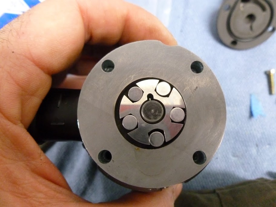
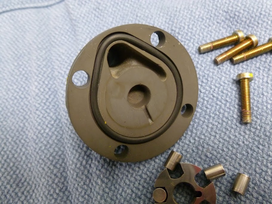
") . Because of that it looked as one part. Because of the print of the rubber ring in the top cap it was clear for me how to mount it back. But because of this thread I was wondering what you ment with the x and y thing. Thanks for the clarification.
. Because of that it looked as one part. Because of the print of the rubber ring in the top cap it was clear for me how to mount it back. But because of this thread I was wondering what you ment with the x and y thing. Thanks for the clarification.