Getrag 265 Fun.

ScottAndrews

Well-Known Member
Messages
422
Reaction score
132
Location
Petaluma, CA
There is another thread asking about noise in the Getrag 265. I was curious about exactly how that trans worked. There were no good diagrams, so, decided to make one. This is based of a sectional view posted some time ago by @Devinder. I added the colors to highlight the various parts.

Here is the transmission in Neutral:
The input shaft on the left is light pink. The output shaft is purple./blue. The bearings are light blue. Some are rollers, so they are hard to see. The lay-shaft is orange, the shift clutches and syncros are maroon, and the gears are various colors. The gear faces that engage the lay shaft are shown in reddish orange.

The input shaft is connected by its gear directly to the lay shaft. So the lay shaft always turns when the input shaft is turning, and all of the colored gears are also turning, because they re meshed with the lay-shaft. This is what is known as a constant mesh gearbox, because the driving gears do not actually ever not mesh. This means that all of the colored gears are spinning all the time at different rates when the input shaft is turning (note all of them are separated from the output shaft by roller bearings (light blue), and this is why this whole thing works. Shifting is a process of selectively connecting the gears with the output shaft.

Screenshot 2025-03-25 at 8.10.24 PM.png


Here is the trans in 1st gear. the aft shift fork has moved the aft dog clutch to the left (yellow arrows). This connects the 1st gear to the output shaft, and thus the torque comes in the input shaft, goes to the lay-shaft, and then gets to the output shaft via the first gear.

Screenshot 2025-03-25 at 8.24.22 PM.png


Here is the trans in 2nd gear. The middle shift fork has moved the middle dog clutch to the right (yellow arrows). This connects the 2nd gear to the output shaft, and thus the torque comes in the input shaft, goes to the lay-shaft, and then gets to the output shaft via the 2nd gear.

Screenshot 2025-03-25 at 8.29.40 PM.png


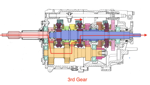
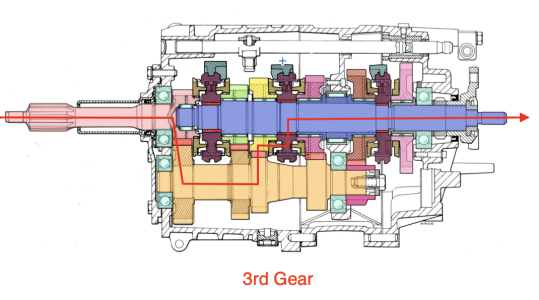
Here is the trans in 3rd gear. The middle shift fork has moved the middle dog clutch to the left (yellow arrows). This connects the 3rd gear to the output shaft, and thus the torque comes in the input shaft, goes to the lay-shaft, and then gets to the output shaft via the 3rd gear.
Screenshot 2025-03-25 at 8.33.41 PM.png


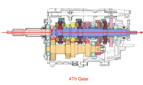
Here is the trans in 4th gear. The forward shift fork has moved the forward dog clutch to the left (yellow arrows). This connects the input shaft to the output shaft to create a 1:1 ratio. Thus the torque comes in the input shaft and goes directly to the output shaft. In this gear the lay-shaft is turning, but it is carrying no load, because none of the gears it engages are connected to the output shaft.
Screenshot 2025-03-25 at 8.40.55 PM.png


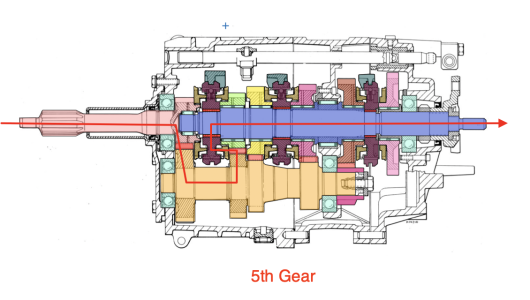
Here is the trans in 5th gear. The forward shift fork has moved the forward dog clutch aft (yellow arrows). This connects the 5th gear to the output shaft, and thus the torque comes in the input shaft, goes to the lay-shaft, and then gets to the output shaft via the 5th gear.

Screenshot 2025-03-25 at 8.46.35 PM.png


And lastly, here is the trans in reverse. The aft shift fork has moved the aft dog clutch to the right (yellow arrows). This connects the reverse gear to the output shaft. There is a secondary lay shaft (not shown in the diagram) that connects the lay shaft to the reverse gear, and thus the torque comes in the input shaft, goes to the lay-shaft, goes to another lay shaft (thereby reversing direction), and then gets connected to the output shaft via the reverse gear.
Screenshot 2025-03-25 at 8.46.46 PM.png


I think this is all correct, but if I have misunderstood then please let me know,.
 
Nice drawing and description. Let's now derive a noise throubleshooting guide based on that.
There are 4 bearings to consider, let's designate them UL, UR, LL, and LR based on their location in the diagram Ignoring their real names for now).

1) Transmission is in neutral, car idles, no motion, clutch pedal depressed: No bearings can be making any noise because none should be spinning.
2) Transmission is in neutral, car idles, car rolling forward, clutch pedal depressed: The only bearing that moves is UR, if we hear noise that one is bad. No noise means UR is good.
3) Transmission is in neutral, car idles, no motion, clutch pedal released: UL, LL, LR are spinning but UR is not. Bearing noise can be any of the three. Noise should be proportional to RPM.
4) Transmission is in forward gear, car idles, car rolling forward, clutch pedal depressed: All bearings should spin and any noise should be proportional to road speed and independent of engine RPM.
5) Transmission is in gear, car accelerated, clutch pedal released: All bearings are spinning, UL, LL, LR proportional to RPM, UR proportional to road speed.

Based on the above it is hard to know which of the UL, LL, LR is noisy unless the load is a factor.
Hi Ariel;
This is exactly why I did this! Good work!. I think load is a factor. Also, while I agree there are 4 ball bearings, there are also seven roller bearings (along the output shaft), although I doubt any of these would cause the noise. These would be under load depending on what gear was selected.

I general, in ANY gear, with the clutch pedal released, the lay shaft will be turning and under load. Every transmission I have rebuilt has had lay shaft issues (although none were as complex mechanically as the 265).

Scott
 
I general, in ANY gear, with the clutch pedal released, the lay shaft will be turning and under load. Every transmission I have rebuilt has had lay shaft issues (although none were as complex mechanically as the 265).

Scott
Except that in 4th gear the layshaft carries no load, a 4th gear noise test has to be very useful for determining if the LL,LR bearings are noise or not, but not sure how.

Next topic would be to understand dog clutches, as smooth shifting is as important as as smooth gears...
 
Since we are exploring the 265 trans, I thought it might be useful to go into the actual shifting process. I assume many of you are already familiar with this, but I hope it might be instructive for those who find gear boxes somewhat mysterious.

Some background: I was semi-fortunate that my dad gave me a car for my 16th birthday. The unfortunate aspect of this was that it was a decrepit Morris Minor 1000 convertible. It belched smoke and 2nd gear was non-existent. So I spent the spring and summer of 1969 pulling and rebuilding the engine and trans. I drove that car all through highschool and part of college. Wish I still had it.. It was cute..

Anyway, rebuilding a transmission from only the exploded diagram causes you to learn a lot!!

You can see in the diagram below the colored gears (green, yellow, magenta, brown, and pink) are positioned in pairs with a dark purple shifter between them. These gears are also always meshed with their corresponding gears on the lay shaft (also called a counter shaft, since it turns counter to the input shaft). Shift Forks (darker green) fit into grooves on the shifters. You can see some actual shift forks in the photo above posted by @Thomas76. One of those is still engaged in its shifter (center left). These forks are actuated by the shift rods (shown uncolored at the top of the image below) so that they slide fore and after depending onthe position of the gear shift lever. The shifters slide on splines on the output shaft (indicated in red). The shift forks are interlocked by small balls that allow only one fork to move at a time (see added anecdote below for a good story!).

Between each shifter and its adjacent gear is a dog clutch (shown in gold). There are six of these, one for each gear-shifter interface.
Screenshot 2025-03-26 at 10.31.28 AM.png

When a shift fork causes a shifter to slide toward a gear it first engages a conical mating surface (these are not really shown well in the diagram) - this is the synchro cone. This cone causes some friction between the shifter and the corresponding gear causing them to spin at more-or-less the same rotational speed. As the shifter slides into position, the shifter engages the dog clutch. The dog clutch has a large number of small teeth that mate with corresponding grooves in the shifter, thereby locking them together, so they spin at the same speed.

It is important to remember that the lay-shaft is driven by the input shaft gear, so it is always spinning when the input shaft is spinning. Since it is constantly meshed with each of the colored gears, and each pair of lay shaft gears and colored gears has some defined gear ratio, the colored gears are all spinning at different rotational speeds.

When the transmission is shifted "into gear", what is really happening is that a shifter is locking one of the spinning colored gears to the output shaft, thereby connecting the input and output shafts together through some rotational ratio determined by the specific combination of gears involved (in all cases other than 4th gear, via the lay-shaft).

So here are a few more detailed diagrams of the torque path in various gears:

Screenshot 2025-03-26 at 11.14.14 AM.png


Screenshot 2025-03-26 at 11.13.02 AM.png


Screenshot 2025-03-26 at 11.14.50 AM.png


I'll leave 2nd and 1st as exercises for the reader... ;)

So for those who read this far. here is the anecdote: When I disassembled my Morris trans, I put all the parts in a big box, and then carefully figured out which parts went where when I re-assembled it. When I was done there was one part left in the box. A single small ball bearing ball. I did not recall any of the bearings themselves missing any balls, and this one was smaller than those anyway. I scoured the exploded diagram I had (which had been copied onto that horrible thermal copy paper we used back then...) to no avail. I finally decided that it must have been in the box from some other project. So I put the trans back in the car and hopped in to take it for a spin. I drove to the Sav-On drug store at the nearby shopping center to get a celebratory ice cream cone (this was pre-beer, of course!). That all went fine, but when I went to drive home, I shifted into first and headed off, shifted into second, and when I let out the clutch there was a horrible crunch and the car stopped. I called my mom from a pay phone (remember those?) who came down in the VW bus with a rope, and we towed the car home. Out came the trans, and I opened it up. My brand new lay-shaft was destroyed.. Apparently the ball was supposed to sit in a small detent between the two shift rods, so that when one was engaged, the ball prevented the other from moving, and vice versa. It was supposed to be removed and installed by removing a small bolt onthe side of thew housing. Apparently it had fallen out unseen when I pulled the shift rods out. Without the ball, the shift forks moved the shifters to engage both second gear and 4th gear, and when I let out the clutch something had to give.. My dad was kind enough to buy me a new lay shaft and I rebuilt the whole trans again.. That time it lasted for several years until I sold the car to buy an MG... So the moral here is never assume a left over part is not important!!
 

Attachments

  • Screenshot 2025-03-26 at 11.14.53 AM.png
    Screenshot 2025-03-26 at 11.14.53 AM.png
    884.4 KB · Views: 32
  • Screenshot 2025-03-26 at 11.07.49 AM.png
    Screenshot 2025-03-26 at 11.07.49 AM.png
    514.5 KB · Views: 0
  • Screenshot 2025-03-26 at 11.06.58 AM.png
    Screenshot 2025-03-26 at 11.06.58 AM.png
    505.2 KB · Views: 1
  • Screenshot 2025-03-26 at 11.04.51 AM.png
    Screenshot 2025-03-26 at 11.04.51 AM.png
    517.5 KB · Views: 1
Last edited:
Except that in 4th gear the layshaft carries no load, a 4th gear noise test has to be very useful for determining if the LL,LR bearings are noise or not, but not sure how.

Next topic would be to understand dog clutches, as smooth shifting is as important as as smooth gears...
HAH!!! you read my mind!

As explained above, the shooting is performed by the dog clutches, but built into them are the synchros which get things rotating at the same speed , so the dog clutches don't grind when they mesh.

And yes, in 4th there is no load on the lay shaft.
 
Last edited:
Here's a photo of a typical dog clutch and synchro. You can see that the clutch dogs will engage the corresponding dogs on the other part while the synchro cone will get the two parts spinning at the same speed, so the dogs are not moving fast relative to one another.
Screenshot 2025-03-26 at 11.57.44 AM.png
 
@ScottAndrews let me know if you want more pics for illustration purposes, I still have a 265 completely torn apart.
OOOOHH! Interesting!

Yes, can you show a pic of a shifter, dog clutch and gear showing what they look like apart and how they mate together? I think that would be very instructive. Maybe the assembly on the right side of the image you posted.

Are you rebuilding the 265? If so, where did you find parts?
 
Last edited:
I don't have any tranny's apart in the shop right now but something else that would be helpful to people would be to show some worn out parts, specifically, where they wear and why There are 2 different kinds of synchro rings, one with serrated steps on the inside to help grab the next gear and ones that have a rough sandpaper type of feel to them, wear in the dog teeth on the gears, wear in the shifter sleeves and on the shift forks just a few things

Thanks, Rick
Yes, that would be great to see, if anyone has such pics! Thanks for the suggestion!
 
Last edited:
Back
Top