Submitted by: Devinder (2002)
This page is still under construction. I will be adding more as I finish installing the transmission in my coupe.
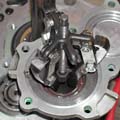
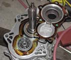
Lotite 573 or gasket shellac
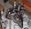
Remove (7) 8mm screws; three are longer. Keep track of the shims used to preload the bearings. The input shaft seal is 35mm ID, 52mm OD, 7mm thick and should be marked with a rotation direction so that it is installed in the correct direction.
 >
> >
>
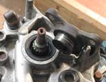
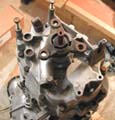
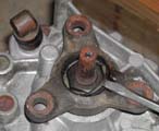
The output flange is secured to the output shaft with a large nut. Because the tip of the output shaft extends beyong the flange, a 30mm deep socket is required to remove the nut. I've found that almost any quality 12pt socket will fit inside the flange after the lock ring is removed. The flange is not pressed onto the output shaft, but it can be a little hard to remove because of the sealant on the splines.
The output flange seal is 40mm ID, 55mm OD, 8mm thick and should also be marked with a rotation direction so that it is installed in the correct direction. When installing, remember to put sealant (Loctite 270) on the splines and thread locker on the flange nut since this is a potential leak path. Use a new lock ring (P/N) -- the old one will not work.
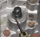
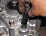
This seal can be pried out with a small screwdriver. Be very careful not to scratch the selector rod or the seal housing. The new seal is easily seated using a deep socket (I used a 5/8").
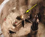
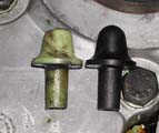
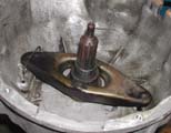
Replace the pivot pin inside the bell housing. This pin is made of plastic and wears down easily. There are after-market pins available made of aluminum. The clutch release arm pivots on this pin and is held onto the pin with a wire clip.
The clutch housing is mounted to the engine block with 8 bolts. The 4-speed and auto trans use different bolt lengths so you will need to get the correct bolts for the 5-speed clutch housing:
You will also need (2) M6x1.0x16 bolts for the cover plate that goes at the bottom of the clutch housing on the engine side. The 4 large studs in the clutch housing are M12x1.75 and the gearbox mounts to the clutch housing with (4) M12 nuts and washers.
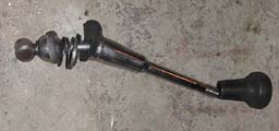
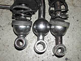

shift rod (also refered to as a "schill rod") is 147mm long, and the ends have 10mm dia by 22mm long shafts.
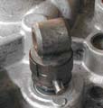
The knuckle at the end of the selector shaft is fastened with a pin. Slide the sleeve back to remove the pin. The new knuckle should come with a piece of foam that fits inside to keep it from rattling.
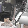
The shift platform is attached to the transmission using two aluminum blocks with rubber bushings in them. Get new ones (P/N) or machine solid blocks to replace the flexible ones. You'll have to change the mounting system entirely if you use solid mounts because with the rear of the platform attached to the tunnel, the realtive movement will loosen the platform. The blocks are attached to the transmission with (2) M8x1.25x40 bolts, and then the shift platform is mounted to the blocks as shown in the picture with (2) M8x1.25x30 bolts.
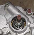
The spedometer drive gear is pressed onto the end of the output shaft. If it is present, then all you need to do is install the speedometer drive pinion from the 4-speed. If the drive gear has been replaced with a spacer, then you will have to remove the spacer and install the drive gear from the 4-speed. The gear can be installed through the opening in the case, but it is much easier with the rear case removed.

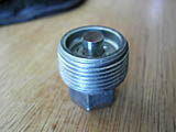
Replace the old socket-head style drain and fill plugs with the newer hex-head plugs. These are much easier to remove and install, and they have a magnetic pickup to trap any particles in the oil.
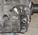
The reverse switch illuminates the reverse lights when the gearbox is in reverse. On a used gearbox, it is likely to be banged up in some way since it is the softest thing on the outside. It's really inexpensive and very difficult to replace once the transmission is installed in the car. Don't forget to put a 12mm crush washer under the new one.
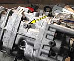
Check this vent on top of the gearbox. If it's clogged, the motion of the gears can build up pressure inside the gearbox and force oil past the seals.
If, after cleaning the outside of the transmission, you dont like the look of the corroded fasteners holding the transmission cases together, you can repalce them with new ones:
With the transmission out, this is the best time to replace these parts. Of course, if you had an automatic transmission then you need to install them anyway. I'm going to assume that you've removed everything (or never had the parts in the first place).
Pilot bearing removal is another story.
Buy the Sachs clutch kit; it comes with a clutch disc, pressure plate, throw-out (clutch release) bearing, and sometimes the pilot bearing and alignment tool. It does not come with the (6) M8x1.25x16 socket head cap screws to attach the pressure plate to your newly resurfaced flywheel.
I could not get my 4-speed crossmember to work at all so I used a 528i crossmember on the "right" ear. Here's a picture:
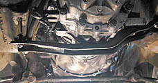
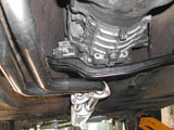
With this mount, when it is perpendiculer to the long axis of the car, you will find that the holes line up exactly where the t-nuts come out of the tracks. I cocked the crossmember until it was in front of the hole on the right and behind the hole on the left. I was still having problems with the cocked crossmember touching the trans and telegraphing gear noise into the cabin, so I ended up drilling additional holes in the cross member to fix the alignment.
(2) M10x1.5 nuts
get new t-bolts (P/N) and M8 lock-nuts
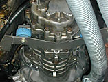
Of course, you could go with a custom mount. This is on Jim Clark's car -- I think it's the metric mechanic mount:
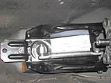
For a CS 5-speed conversion, you need to shorten the drive shaft by 95 mm (3.75"). Alternativley you can use a CS automatic transmission driveshaft. The auto driveshaft is only about 3/4" shorter in overall length than the correct 5-speed length, but the problem is that the rear section is not the same length as a 4-speed shaft so you have to stretch the center bearing. Here's a picture of the 4-speed D/S and auto D/S with the ass ends aligned:
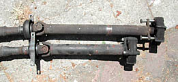
I couldn't believe this so I measured the bearing mount on the parts car. Turns out the auto trans cars have the center bearing mounts welded about an inch closer the front of the car. The upper D/S is from my 73 3.0CS 4-speed, and the lower one is from a 71 2800CS auto. As you can see, the rear section is longer on the auto D/S. You can make up the overall 3/4" length by sliding out the splines (in fact, you have to do that). But, since the center bearing is attached to the front portion, this makes the problem worse. I fixed it by reversing the direction of the center bearing. Even with this, The rubber membrane on the bearing is really stretched out and I don't expect it to last very long.
Also, the guibo flange bolt holes on the D/S are different sizes. The 4-speed has 12mm holes on the D/S flange and on the trans output flange. The auto has 10mm holes. So, you have to use 12mm bolts on the trans side and 10mm bolts on the D/S side when you mount the auto D/S to the 5-speed.
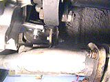
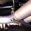
The center exhaust mount has to modified a bit. There are many ways of doing it, and the one shown in the pictures is probably the easiest because it can be made with the fewest fabricated parts. I believe you need the 2800CS auto-trans exhaust mount to make this work. These pictures were taken by TJ Noto on his installation:
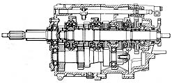
Getrag 256 Prep
This page is still under construction. I will be adding more as I finish installing the transmission in my coupe.
Specifications

| Gear ratios | |||
| 1st | 3.82 : 1 | ||
| 2nd | 2.20 : 1 | ||
| 3rd | 1.40 : 1 | ||
| 4th | 1.00 : 1 | ||
| 5th | 0.81 : 1 | ||
| reverse | 3.71 : 1 | ||
| speedometer drive | 2.5 : 1 (teeth 10/4) | ||
| Shaft end-play | |||
| input shaft | 0 to 0.09 (0 to 0.0035) | mm (inches) | |
| output shaft | 0 to 0.09 (0 to 0.0035) | mm (inches) | |
| countershaft | 0.1 to 0.2 (0.004 to 0.008) | mm (inches) | |
| Lubricant capacity | 1.7 (1.6) | quarts (litres) | |
| Torques | |||
| gearbox to clutch housing | 52 to 58 (72 to 78) | lbf-ft (N-m) | |
| drain and fill | 29 to 43 (40 to 60) | lbf-ft (N-m) | |
| front cover | 13 to 18 (18 to 25) | lbf-ft (N-m) | |
| output flange | 72 (100) | lbf-ft (N-m) | |
| cross-member to body | 16 to 17 (22 to 24) | lbf-ft (N-m) |
Seals
Input Shaft


Lotite 573 or gasket shellac
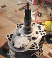
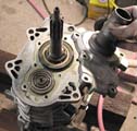
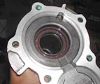
Remove (7) 8mm screws; three are longer. Keep track of the shims used to preload the bearings. The input shaft seal is 35mm ID, 52mm OD, 7mm thick and should be marked with a rotation direction so that it is installed in the correct direction.
Output Flange
 >
> >
>

The output flange is secured to the output shaft with a large nut. Because the tip of the output shaft extends beyong the flange, a 30mm deep socket is required to remove the nut. I've found that almost any quality 12pt socket will fit inside the flange after the lock ring is removed. The flange is not pressed onto the output shaft, but it can be a little hard to remove because of the sealant on the splines.
The output flange seal is 40mm ID, 55mm OD, 8mm thick and should also be marked with a rotation direction so that it is installed in the correct direction. When installing, remember to put sealant (Loctite 270) on the splines and thread locker on the flange nut since this is a potential leak path. Use a new lock ring (P/N) -- the old one will not work.
Selector Shaft


This seal can be pried out with a small screwdriver. Be very careful not to scratch the selector rod or the seal housing. The new seal is easily seated using a deep socket (I used a 5/8").
Clutch Housing


Replace the pivot pin inside the bell housing. This pin is made of plastic and wears down easily. There are after-market pins available made of aluminum. The clutch release arm pivots on this pin and is held onto the pin with a wire clip.
The clutch housing is mounted to the engine block with 8 bolts. The 4-speed and auto trans use different bolt lengths so you will need to get the correct bolts for the 5-speed clutch housing:
- (2) M10x1.5x95
- (2) M10x1.5x35 [near starter]
- (1) M8x1.25x90
- (2) M8x1.25x35 [near head]
- (1) M8x1.25x40 [through-bolt with nut]
You will also need (2) M6x1.0x16 bolts for the cover plate that goes at the bottom of the clutch housing on the engine side. The 4 large studs in the clutch housing are M12x1.75 and the gearbox mounts to the clutch housing with (4) M12 nuts and washers.
Shifter


shift rod (also refered to as a "schill rod") is 147mm long, and the ends have 10mm dia by 22mm long shafts.
Shift Platform

The knuckle at the end of the selector shaft is fastened with a pin. Slide the sleeve back to remove the pin. The new knuckle should come with a piece of foam that fits inside to keep it from rattling.

The shift platform is attached to the transmission using two aluminum blocks with rubber bushings in them. Get new ones (P/N) or machine solid blocks to replace the flexible ones. You'll have to change the mounting system entirely if you use solid mounts because with the rear of the platform attached to the tunnel, the realtive movement will loosen the platform. The blocks are attached to the transmission with (2) M8x1.25x40 bolts, and then the shift platform is mounted to the blocks as shown in the picture with (2) M8x1.25x30 bolts.
Speedometer Drive

The spedometer drive gear is pressed onto the end of the output shaft. If it is present, then all you need to do is install the speedometer drive pinion from the 4-speed. If the drive gear has been replaced with a spacer, then you will have to remove the spacer and install the drive gear from the 4-speed. The gear can be installed through the opening in the case, but it is much easier with the rear case removed.
Other


Replace the old socket-head style drain and fill plugs with the newer hex-head plugs. These are much easier to remove and install, and they have a magnetic pickup to trap any particles in the oil.

The reverse switch illuminates the reverse lights when the gearbox is in reverse. On a used gearbox, it is likely to be banged up in some way since it is the softest thing on the outside. It's really inexpensive and very difficult to replace once the transmission is installed in the car. Don't forget to put a 12mm crush washer under the new one.

Check this vent on top of the gearbox. If it's clogged, the motion of the gears can build up pressure inside the gearbox and force oil past the seals.
If, after cleaning the outside of the transmission, you dont like the look of the corroded fasteners holding the transmission cases together, you can repalce them with new ones:
- (8) M8x1.25x55 hex-head bolts (7 with nuts)
- (4) M8x1.25x50 hex-head bolts
- (10) M8x1.25x35 socket-head cap screws
Remove Old Transmission


Clutch, Pilot Bearing, and Crankshaft Rear Main Seal


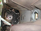
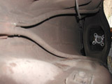
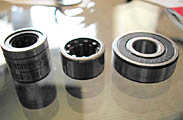
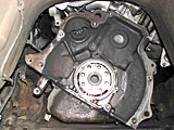
With the transmission out, this is the best time to replace these parts. Of course, if you had an automatic transmission then you need to install them anyway. I'm going to assume that you've removed everything (or never had the parts in the first place).
Pilot bearing removal is another story.
Buy the Sachs clutch kit; it comes with a clutch disc, pressure plate, throw-out (clutch release) bearing, and sometimes the pilot bearing and alignment tool. It does not come with the (6) M8x1.25x16 socket head cap screws to attach the pressure plate to your newly resurfaced flywheel.
Rear Transmission Mount
I could not get my 4-speed crossmember to work at all so I used a 528i crossmember on the "right" ear. Here's a picture:


With this mount, when it is perpendiculer to the long axis of the car, you will find that the holes line up exactly where the t-nuts come out of the tracks. I cocked the crossmember until it was in front of the hole on the right and behind the hole on the left. I was still having problems with the cocked crossmember touching the trans and telegraphing gear noise into the cabin, so I ended up drilling additional holes in the cross member to fix the alignment.
(2) M10x1.5 nuts
get new t-bolts (P/N) and M8 lock-nuts

Of course, you could go with a custom mount. This is on Jim Clark's car -- I think it's the metric mechanic mount:
Shifter Mount

Drive Shaft
For a CS 5-speed conversion, you need to shorten the drive shaft by 95 mm (3.75"). Alternativley you can use a CS automatic transmission driveshaft. The auto driveshaft is only about 3/4" shorter in overall length than the correct 5-speed length, but the problem is that the rear section is not the same length as a 4-speed shaft so you have to stretch the center bearing. Here's a picture of the 4-speed D/S and auto D/S with the ass ends aligned:

I couldn't believe this so I measured the bearing mount on the parts car. Turns out the auto trans cars have the center bearing mounts welded about an inch closer the front of the car. The upper D/S is from my 73 3.0CS 4-speed, and the lower one is from a 71 2800CS auto. As you can see, the rear section is longer on the auto D/S. You can make up the overall 3/4" length by sliding out the splines (in fact, you have to do that). But, since the center bearing is attached to the front portion, this makes the problem worse. I fixed it by reversing the direction of the center bearing. Even with this, The rubber membrane on the bearing is really stretched out and I don't expect it to last very long.
Also, the guibo flange bolt holes on the D/S are different sizes. The 4-speed has 12mm holes on the D/S flange and on the trans output flange. The auto has 10mm holes. So, you have to use 12mm bolts on the trans side and 10mm bolts on the D/S side when you mount the auto D/S to the 5-speed.
Exhaust Mount
The center exhaust mount has to modified a bit. There are many ways of doing it, and the one shown in the pictures is probably the easiest because it can be made with the fewest fabricated parts. I believe you need the 2800CS auto-trans exhaust mount to make this work. These pictures were taken by TJ Noto on his installation:


