And educational tools!!I am not ambitious enough to attempt a rebuild! I was given a bad trans to rob the shift rod. It was fun to take apart, now I have spare parts.
You are using an out of date browser. It may not display this or other websites correctly.
You should upgrade or use an alternative browser.
You should upgrade or use an alternative browser.
Getrag Transmission Fun.
- Thread starter ScottAndrews
- Start date
If nothing else I'm glad at least 1 other person in this world geeks out with mechanical things like I do.And educational tools!!
")
I also have a getrag 4 speed disassembled on reserve for when we get bored with 5 speeds.
Still on the topic of synchros and dog clutches, I found this good photo. I think this is slightly different fromthe 265 synchro, but it gets the point across.

Here we have the shifter on the left, and a gear on the right. Remember the shifter has two parts, the outer part with the circumferential groove engages the shifting fork, the inner part is splined to the output shaft. You can see the spline in the photo. The outer part slides on the inner part along a set of teeth that go all the way around the circumference of the inner part (sort of a large diameter spline). This is the "dog clutch".
The gear has a set of teeth that have the same diameter and pitch as the inner part of the shifter. You can see these onthe left side of the right hand gear.
The bronze synchro ring sits between the shifter and the gear. It has a conical inside surface that engages that conical surface of the gear, which you can see between the ring and the gear, and a set of teeth that also match the outer spline teeth (the "dogs") on the inner part of the shifter. When the outer part of the shifter slides to the right in this photo, it will first engage the teeth on the synchro ring, causing it to move slightly against the conical section of the gear. This will cause the gear to change its rotational speed to match the shifter. The shifter continues to slide right until the teeth on the outside of the shifter engage the dog teeth on the gear. At that point the gear is locked to the inner part of the shifter by the outer part of the shifter, and since the inner part of the shifter is splined to the shaft, the gear is now locked to the shaft.
That is a useful analysis and picture Scott. Two intriguing questions remain in terms of the details, 1) how does the non-linear motion (H pattern) of the shift lever gets translated into a linear and gradual displacement of what you call shifter in the picture; 2) the gear helicoidal teeth on the right, do they engage/disengage when shifting, or are they always engaged but they get attached/detached from the shaft and that is all?
When I fail a shift and hear the dreaded gear impact noise, I always imagine gear teeth not meshing, but it is perhaps dog clutch teeth making that noise.
When I fail a shift and hear the dreaded gear impact noise, I always imagine gear teeth not meshing, but it is perhaps dog clutch teeth making that noise.
The helical gears are always engaged. The selectable gears (1 through 5) are mounted to the output shaft on roller bearings. So, they ordinarily just spin on the shaft. They are always engaged with their counterpart gears on the lay-shaft, and so, if the input shaft is spinning, each of the selectable gears is spinning at a speed related to the gear ratio.That is a useful analysis and picture Scott. Two intriguing questions remain in terms of the details, 1) how does the non-linear motion (H pattern) of the shift lever gets translated into a linear and gradual displacement of what you call shifter in the picture; 2) the gear helicoidal teeth on the right, do they engage/disengage when shifting, or are they always engaged but they get attached/detached from the shaft and that is all?
When I fail a shift and hear the dreaded gear impact noise, I always imagine gear teeth not meshing, but it is perhaps dog clutch teeth making that noise.
To select a gear, you move the corresponding shift fork and that moves the shifter to engage the dog clutch as I described above. The dog clutch locks the selected gear to the output shaft completing the torque flow from input shaft to the lay shaft, to the selected gear, to the shifter and then to the output shaft.
The crunching sound you hear when you miss a shift is the dog teeth grinding together.
Here is a simplified diagram of the shifters and gears going from neutral to one gear and then the other.
The shift forks get moved by the shift rods, which have small tabs on the ends that engage a mating tab on the main shift lever (the gearshift part the driver moves). As the gear lever is moved right to left, it engages one of the three shift rods. Moving the gear lever forward or backward then causes the fork attached to that selected rod to move forward or aft to move the corresponding shift fork. Here is a simple diagram of this part.
Last edited:
The helical gears are always engaged. The selectable gears (1 through 5) are mounted to the output shaft on roller bearings. So, they ordinarily just spin on the shaft. They are always engaged with their counterpart gears on the lay-shaft, and so, if the input shaft is spinning, each of the selectable gears is spinning at a speed related to the gear ratio.
That is what I suspected for practical reasons. Helical gears are coupled at the factory, no play, no need to engage ever again.
That makes the role of the roller bearings hugely important, if they ever start developing friction then it is as if you are driving on two different gears at the same time... Imagine you are in 5th gear but the second gear roller has 50% friction, it effectively causes your own engine to operate as a brake towards the driveshaft, as if you kind of downshifted. It would be noisy and develop some heat I guess.
I assume a transmission rebuild starts with replacing all roller bearings...
Now I get the shift rods and why the H pattern.
Lateral motion selects which rod, back and forth determines towards which gear it moves.
Last edited:
Yes, For a 5 speed there are actually 4 shift rods. One for reverse, one for 5th, and two for the 1-2-3-4 H-pattern.That is what I suspected for practical reasons. Helical gears are coupled at the factory, no play, no need to engage ever again.
That makes the role of the roller bearings hugely important, if they ever start developing friction then it is as if you are driving on two different gears at the same time... Imagine you are in 5th gear but the second gear roller has 50% friction, it effectively causes your own engine to operate as a brake towards the driveshaft, as if you kind of downshifted. It would be noisy and develop some heat I guess.
I assume a transmission rebuild starts with replacing all roller bearings...
Now I get the shift rods and why the H pattern.
Lateral motion selects which rod, back and forth determines towards which gear it moves.
The 265/6 5 speed has a sort of tenedor del diablo shift pattern, with reverse far left and forward, first left and forward, 2nd left and back, 3rd left and forward, 4th left and back, and 5th far right and forward.
265/6
265/5 (CR)
Nice CAD work for the visuals!
Fascinating, here is an open transaxle for a FWD car. Still 5-speed. The straight cut gears on the left are presumably reverse, and then 1st through 5th in sequence to the right. The notable part is that the input and output face the front of the car so presumably the shafts are one inside the other with a bearing or more in between...
Attachments

Interesting.. I am wondering if the input shaft goes through the output shaft, making the input gear the one on the far right.Fascinating, here is an open transaxle for a FWD car. Still 5-speed. The straight cut gears on the left are presumably reverse, and then 1st through 5th in sequence to the right. The notable part is that the input and output face the front of the car so presumably the shafts are one inside the other with a bearing or more in between...
Not sure.Interesting.. I am wondering if the input shaft goes through the output shaft, making the input gear the one on the far right.
Last edited:
I'm sure this has been covered before, but I thought it would be useful to compare the gear ratios in the typical E9 transmissions:

Notably, the ratios of the 262 and 265/6 are very similar (within about 6% of one another), with the exception of the overdrive 5th. So, presumably the drivability of a 265/6 in an E9 should be pretty good, with a bit higher top end speed. In contrast, the CR trans has much lower ratios (6%, 15%, 22% and 25% respectively from 1st to 4th.
Notably, the ratios of the 262 and 265/6 are very similar (within about 6% of one another), with the exception of the overdrive 5th. So, presumably the drivability of a 265/6 in an E9 should be pretty good, with a bit higher top end speed. In contrast, the CR trans has much lower ratios (6%, 15%, 22% and 25% respectively from 1st to 4th.
Last edited:
Been looking for a cut away side-view of the Getrag 262 4 speed. If anyone has one, please post it, and I'll color it like I did the 265.
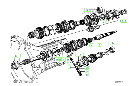
In the meantime, here is an exploded view from the 262.
The basic architecture of the trans is close to the 265 above. You can easily identify the corresponding parts (just one fewer gear set).
To make sense of this, in the top stack of parts you can see the roller bearings for the gears, and the two piece (inner and outer) shifter. All of that strings onto the output shaft from the rear. The middle set is the input shaft, and a stack that fits onto the output shaft from the front. There is another shifter on that stack. I have numbered the gears (4th is straight through).
Attachments
Last edited:
Hi guys
I drove my car last week for the first time and the 265 5 speed sounds a bit like a supercharger ( unfortunately)
She is very whiny
So I will probably have to do a rebuild on it .
Does anyone know which parts I should focus on and if they are still available for sale somewhere ?
or perhaps have any recommendations maybe for specialists who actually do rebuilds on them ?
I would prefer if there was someone nearby, but that might not be possible as I’m in Ireland so perhaps someone in the UK or Central Europe, the closer the better.
Anyway any advice would be greatly appreciated
Thanks again
I think Metric Mechanic rebuilds these in the US. Not sure about sources in the EU.
It's hard to tell what parts need replacement without opening up the trans. You can expect to replace all the beatings and the bronze synchro cones. If the whining has not gone on too long then that maybe all the is needed. If any of the great has been wearing due to improper engagement because of a worn bearing then that gear will probably need replacement (ad likely the lay shaft, since it will have the mating gear.
I hear parts are hard to find...
I see Metric Mechanic sells a rebuilt 265 either CR or OD for $4500. I'm pretty sure you would need to provide your old one as a core.

 metricmechanic.com
It's hard to tell what parts need replacement without opening up the trans. You can expect to replace all the beatings and the bronze synchro cones. If the whining has not gone on too long then that maybe all the is needed. If any of the great has been wearing due to improper engagement because of a worn bearing then that gear will probably need replacement (ad likely the lay shaft, since it will have the mating gear.
I hear parts are hard to find...
I see Metric Mechanic sells a rebuilt 265 either CR or OD for $4500. I'm pretty sure you would need to provide your old one as a core.
See All Metric Mechanic Ultimate Transmissions
A Metric Mechanics Ultimate Transmission is a re-designed Getrag or ZF manual transmission that can be shifted more aggressively and is designed to last far longer than a BMW factory or conventional rebuild. With over 4 decades of experience, MM has developed a stellar reputation for building...
In any condition if the engine is running and clutch not depressed three of the roller bearings are spinning... they can never be separated from each other....Nice drawing and description. Let's now derive a noise throubleshooting guide based on that.
There are 4 bearings to consider, let's designate them UL, UR, LL, and LR based on their location in the diagram Ignoring their real names for now).
1) Transmission is in neutral, car idles, no motion, clutch pedal depressed: No bearings can be making any noise because none should be spinning.
2) Transmission is in neutral, car idles, car rolling forward, clutch pedal depressed: The only bearing that moves is UR, if we hear noise that one is bad. No noise means UR is good.
3) Transmission is in neutral, car idles, no motion, clutch pedal released: UL, LL, LR are spinning but UR is not. Bearing noise can be any of the three. Noise should be proportional to RPM.
4) Transmission is in forward gear, car idles, car rolling forward, clutch pedal depressed: All bearings should spin and any noise should be proportional to road speed and independent of engine RPM.
5) Transmission is in gear, car accelerated, clutch pedal released: All bearings are spinning, UL, LL, LR proportional to RPM, UR proportional to road speed.
Based on the above it is hard to know which of the UL, LL, LR is noisy unless the load is a factor.
really the only noise that is fairly easy to diagnose is the input shaft bearing. With the car in neutral, if you release the clutch, you may be able to hear the input shaft spinning.
Trying to hear the other bearing seems like a waste of time, since as soon as the clutch is released all of the gears are spinning except the aft output shaft bearing.
Trying to hear the other bearing seems like a waste of time, since as soon as the clutch is released all of the gears are spinning except the aft output shaft bearing.
Okayreally the only noise that is fairly easy to diagnose is the input shaft bearing. With the car in neutral, if you release the clutch, you may be able to hear the input shaft spinning.
Trying to hear the other bearing seems like a waste of time, since as soon as the clutch is released all of the gears are spinning except the aft output shaft bearing.
So I drove my car again this weekend.
The only quiet gear in the 5 speed gearbox is 4th gear
All of the others are winey
With the engine running and the gearbox in neutral she sounds rattely and when I press in the clutch,that noise goes away.
As I bought the gearbox second hand it was a bit of an unknown . So for now I might see if putting different oil in or something might help
Some heavier oil might help for a bit. Sawdust is known to quiet them !Okay
So I drove my car again this weekend.
The only quiet gear in the 5 speed gearbox is 4th gear
All of the others are winey
With the engine running and the gearbox in neutral she sounds rattely and when I press in the clutch,that noise goes away.
As I bought the gearbox second hand it was a bit of an unknown . So for now I might see if putting different oil in or something might help
Seriously if the whining is in every gear but 4th then it is the lay shaft bearings. 4th goes straight through from the input shaft to the output shaft. In that gear the lay shaft is still spinning but it is not under any load. Probably rebuild able though. New bearings and synchros and it should be good for another 150k