how to reset the carbs

I will try to explain my setup a little more clearly:

1- which is the meassuring ratio of the manometers that you are using ? (please give the figure in bar or p.s.i. )

As 61Porsche linked to, the home-made adapters are holding air meters which tell you how much air is going into each carb, when the meters read the same then the carbs are in sync and the meters will also show you airflow both during idle and through the rev range so you can check idle settings and linkage settings as the throttle is moved. I think these meters are preferable to the home made Manometer because there is no risk of sucking the fluid out of one side as you play with the settings of the carbs.

2- in the figure it seems that the manometer mouth is closing completely your device,but this is not possible because then air will not be entering in the carbs, so i suppose that a hole will be somewhere, is this right ? is so, which is the diameter of that hole ?

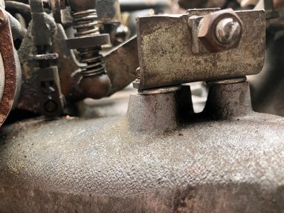
If you look in the background of the picture I posted you will notice 2 clear plastic tubes coming from the engine, those are connected to my home made Manometer and are connected to the vacuum ports which you have circled in green. It looks like this, except my tubes to the device are 10 feet long each:

http://www.powerchutes.com/manometer.asp

I believe in overkill, which is why I use both techniques
:mrgreen:

regards
 
I will try to explain my setup a little more clearly:

there is still a misunderstanding, probably due to my use of english words

lets say that i understand all you toldmeabout those long transparent tubes with a dense fluid inside, that you connect to the pipes in the left side of the carbs, end of part1

now it comes part2, where my questions arise, the incredible device that you designed and built is composed of some plastic and rubber and duck tape together with a suction meter placed on each top (which i probably wrongly named after "manometer")

so my questions were:

1-which is the ratio of the scale of this meter (when you buy a meter you should define in which ratio it is going to work, if you are going to meassure 4 to 8 bar, the meter scale of the meter should be from 0 to 10, because if you use a meter which scale is from 0 to 100, you will not notice the meassurement, do we agree on this ? )

2-if you place a closed cap in the carb, no air will pass through it, and no air will reach the carb, so the engine will not work, thus i suppose that your device must have a hole (not a big one) to allow some air pass through to reach the carb, my question is that if this is true, mayyou tell me which is the size of that hole.

thank you for your understanding and help

regards
 
The meters, named "STE Syncrometer" (sometimes spelled "STE Synchrometer") are made just for carburetor tuning, I purchased them online, (see the link that 61Porsche posted as an example:

http://www.alamomotorsports.com/weber/synchronizers.html

if you do a web search on the "STE Syncrometer" (or "STE Synchrometer") name it should come up with a supplier of them in Spain and/or Europe. The meters work great, the only work is getting them to fit onto the carburetor top - that is what all those plumbing parts are for - to get the meter to fit to the carb with no air leaking. You can use 1 and switch between carbs to get the reading but 2 will allow you to see slight changes when revving the engine.

I believe the scale is in Kg per hour, and goes from 0 - 20, I dont pay attention to the amount, only that they are equal from carb to carb. My car idles at about 16 on the scale. There is a hole on the side that can be switched in to lower the scale and make it less sensitive for revving the engine.

They do have slots/holes in them through which the air passes, and when installed do not cause the engine idle to drop, they are very well made devices. The link above will show you what they look like.

I purchased mine here, they are less expensive than other places, you want the "BK" model.

http://www.cbperformance.com/catalog.asp?ProductID=572

If you need any more info, keep asking!
 
Last edited:
The meters, named "STE Syncrou need any more info, keep asking!


sorry, sorry, sorry, i beg your pardon

i did not saw the explanation that jerry gave me about them

now i understand, it is a prepared device for the syncro test, you buy it and install it and that´s all

let me explain that it was my intention to understand the concept, and replicate it using basic industrial equipment, but i think that it will be fairly more sensible to buy them

thank you both very much

regards
 
Last edited:
Testing 1,2,3....

The synchrometer is a rotary measurement device. Air enters the side through slots. A version of a Petot meter.

For discussion purposes of measurement and what the reference should be in general terms;

Where: required CFM = (engine displacement (c.i.d.) * maximum rpmï's) / 3456

Note: 1 liter = 61.3 c.i.d
  • 3 liter motor = (182 * 6500) / 3456 = 342 CFM​
  • 3.3 liter motor = (200 * 6500) / 3456 = 376 CFM​
  • 3.5 liter motor = (213 * 6500) / 3456 = 399 CFM​
( For you hotrodders, pls. note the above figures do not take effiency into account. Normal decrease anticipated could be 7% or greater.)​


Therefore, wether the measurement is in/ mercury column ( or similar) or ci/air the max at full throttle to anticipate is 400CFM. If there is a device readily available where you are and can measure differential across the gauge with two openings, this figure would be the reference. In practice, 1/2 would suffice.​

Looking closely at the factory synchronizaton device covering the carb there are two openings- one larger than the air cleaner stud which I approximate at 1" and a small opening to attach a tube which in turn is connected to the meter. The 1" opening allows for the cap to sit over the stud and allow air for combustion. The stud could be removed and the cap shorter. For Steve's example- the opening had to be of a size to allow the specific meter he used to fit. The device itself allowed a given amount of air through it for the engine to run. A simpler version of Steve's would be a cylinder, cap, with required measuring opening. ( VW guys have this for stacks)​

Back to the purpose- it's to get an equal measured amount of air flowing in both carburators at idle rpm. Since the carb total flow is a given relative to the throat size opening and the CI of the engine, only the equal flow is important at idle first as this is where the position of the throttle plate and idle flow must be set first in order for the proper mixture to remain constant as throttle opening is increased.​

I hope this helps explain further...and it's ok that there's a slight diffrence in the language dept. It makes it interesting!​

Keep asking questions. Yes, we can talk webers,,, pls. start a new thread though just to keep it simple.​
 
Last edited:
Old thread, so after looking at the linkage on my 2800cs, I’ve come to the conclusion that the factory linkage bar was not made correctly, that or
the geometry is wrong there, the linkage bar mounts to the intakes. Visually the linkage bar stands have different heights appears the rear linkage bar stand is about 3/16 to 1/4 shorter than the front linkage bar stand. Assuming the mounting points on the intakes are the same height, but difficult to tell going to measure it tomorrow. The reason I’m here is that I can’t get the rear carburetor to fully open the primary barrel, visually can’t get the carburetor to open all the way even though my linkages are adjusted, the only way I can get the rear carburetor to open all the way is to adjust the plastic nylon rod length shorter, the problem then is that rear carburetor won’t return to the butterfly back to idle position so the butterfly is open more than the front carburetor. Going to shim the rear carburetor stand tomorrow about 3/16 see how much closer the rear carburetor opens. I would think that from the factory the linkage bar stands are machined to the same plain but perhaps I’m wrong, anyone else see this issue with the rear carburetor not opening all the way ?
 
Perhaps a PO has installed incorrect mounts on which the linkage bar pivots?
Can you post some pics with measurements of the various parts, so we can help in narrowing down your problem?

I'd say that your car left the factory in a nice working order; they are Germans after all. Likely something was replaced with a incorrect part, or is now worn.
For example; various linkage bars exist.
 
I figured it out after sleeping on it, had to shim the rear throttle shaft stand with 1/8” washers apparently the intakes throttle shafts stand points are not are not parallel with each other either, and nor are the stand heights. So need to get the ball joints ball locations associated as close to level as possible. Basically since there are two linkages between the linkage bar, and the actual carburetor throttle any slight difference between them
will amplify the actual link bar input. I was scratching my head for couple days looking for bent parts on the carburetors, adjusting, and readjusting, after doing that several times I started looking at the actual linkage bar, and removed it visually found the linkage bar stands height were different, but assuming that BMW Germany would have been spot on with castings and linkage bar mounts, and the linkage bar was made correctly, but that was not the case. I’m assuming all 2800cs and 3.0 e9 and e3 have this issue if the jig they used to
make the linkage bars is wrong, lol…. I have two 2800cs motors now so will have a look at my other engine that is in the car to confirm the manufacturing defects of those components or if they somehow updated them at some point. Pretty easy to spot if your rear throttle plate is not opening fully then you have a customer, I think it prevents the secondary throttle plates from opening if that rear carb is not fully opening not to mention metered fuel at different throttle points
 
Two washers and some tweaking of the linkage bar success!
 

Attachments

  • IMG_6082.jpeg
    IMG_6082.jpeg
    787.6 KB · Views: 23
  • Like
Reactions: Dlc
I figured it out after sleeping on it, had to shim the rear throttle shaft stand with 1/8” washers apparently the intakes throttle shafts stand points are not are not parallel with each other either, and nor are the stand heights. So need to get the ball joints ball locations associated as close to level as possible. Basically since there are two linkages between the linkage bar, and the actual carburetor throttle any slight difference between them
will amplify the actual link bar input. I was scratching my head for couple days looking for bent parts on the carburetors, adjusting, and readjusting, after doing that several times I started looking at the actual linkage bar, and removed it visually found the linkage bar stands height were different, but assuming that BMW Germany would have been spot on with castings and linkage bar mounts, and the linkage bar was made correctly, but that was not the case. I’m assuming all 2800cs and 3.0 e9 and e3 have this issue if the jig they used to
make the linkage bars is wrong, lol…. I have two 2800cs motors now so will have a look at my other engine that is in the car to confirm the manufacturing defects of those components or if they somehow updated them at some point. Pretty easy to spot if your rear throttle plate is not opening fully then you have a customer, I think it prevents the secondary throttle plates from opening if that rear carb is not fully opening not to mention metered fuel at different throttle points
Good work! I have learned, with these 50+ year old cars, they really need the driver to look closely, and observe what is really going on, and often discover there is some minor tweakcthat can cure a symptom that may seem complex when spoken about in a question to others. Happy you had the patience and resolve to gather the facts and figure out a solution. Will be even more fun to drive now, I am sure! :cool:
 
Good work! I have learned, with these 50+ year old cars, they really need the driver to look closely, and observe what is really going on, and often discover there is some minor tweakcthat can cure a symptom that may seem complex when spoken about in a question to others. Happy you had the patience and resolve to gather the facts and figure out a solution. Will be even more fun to drive now, I am sure! :cool:
This was my experience with linkage adjustments. Look closely, observe the movement, and go from there.
 
Back
Top