Would appreciate any thoughts/insight regarding appropriate mounting of the E9 unibody to a rotisserie/frame rack for the purposes of sill replacement and general metal/body/paint work.
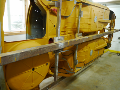
Given the sensitive/flexible nature of the pillarless coupe design, it is obvious that appropriate support of the unibody throughout the deconstruction/reconstruction process of both structural elements (ie sills) and less structural elements/body panels is crucially essential to maintaining overall dimensional conformity and retaining the panel gaps established during metalwork/bodywork in the final, road-going product.
I have seen a variety of body dolly/rotisserie approaches on this site, however I notice that many of these support the body at the front and rear subframe attachment points, which I am suspect of. When the car is fully assembled and on wheels/tires, the weight of the completed car is not supported by the subframe attachment points, but rather by the springs via forward strut tower/mount locations and the rear upper spring perch.
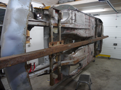
With this in mind, it seems logical that supporting the unibody from these same load bearing structures (strut mounts and rear spring perches) should be the most reliable way to ensure/preserve dimensional conformity and panel gaps when the sill structure is removed and replaced and other body work is conducted. I interpret as further evidence of this the change of door closure/gaps often exhibited by E9s when placed on a lift via the “typical” locations (forward unibody rails and rear sf mounting points). Additionally, does not selecting rear subframe mounting points for support obstruct access to this area (rear of sill/lower wheelhouse area) for reconstruction/metalwork?
Has anyone here constructed a frame rack/rotisserie configuration that attaches to the unibody at the strut tower/rear spring perch locations where it will naturally be supported by the springs when fully assembled? My objective is to ensure that chassis dimensions and panel alignment are preserved precisely as established in body work, and there are no unfortunate surprises when the car is reunited with the pavement later on.
Again, appreciate any thoughts/insight that the community may be able to offer on this topic!
Given the sensitive/flexible nature of the pillarless coupe design, it is obvious that appropriate support of the unibody throughout the deconstruction/reconstruction process of both structural elements (ie sills) and less structural elements/body panels is crucially essential to maintaining overall dimensional conformity and retaining the panel gaps established during metalwork/bodywork in the final, road-going product.
I have seen a variety of body dolly/rotisserie approaches on this site, however I notice that many of these support the body at the front and rear subframe attachment points, which I am suspect of. When the car is fully assembled and on wheels/tires, the weight of the completed car is not supported by the subframe attachment points, but rather by the springs via forward strut tower/mount locations and the rear upper spring perch.
With this in mind, it seems logical that supporting the unibody from these same load bearing structures (strut mounts and rear spring perches) should be the most reliable way to ensure/preserve dimensional conformity and panel gaps when the sill structure is removed and replaced and other body work is conducted. I interpret as further evidence of this the change of door closure/gaps often exhibited by E9s when placed on a lift via the “typical” locations (forward unibody rails and rear sf mounting points). Additionally, does not selecting rear subframe mounting points for support obstruct access to this area (rear of sill/lower wheelhouse area) for reconstruction/metalwork?
Has anyone here constructed a frame rack/rotisserie configuration that attaches to the unibody at the strut tower/rear spring perch locations where it will naturally be supported by the springs when fully assembled? My objective is to ensure that chassis dimensions and panel alignment are preserved precisely as established in body work, and there are no unfortunate surprises when the car is reunited with the pavement later on.
Again, appreciate any thoughts/insight that the community may be able to offer on this topic!
") ), and you can use it as a dolly as well.
), and you can use it as a dolly as well.") All i have to do is build the frame to hold these 6 mounts (see the really big 15x15cm 5x5 inch blue steel tube's?)
All i have to do is build the frame to hold these 6 mounts (see the really big 15x15cm 5x5 inch blue steel tube's?)