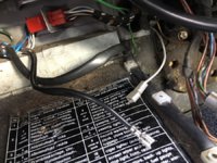
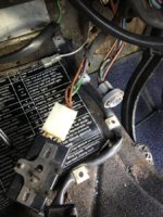
Before I go diving deep under there, accompanied by the trusty wiring diagram, I thought I would ask here in case someone has been there before.
I have several wires which are dangling unconnected to anything under the steering column and around the fuse box area. The strange part is that a few of them are multi pin connectors with seemingly no matching male or female plug anywhere... Do any of these jump out at you as being an obvious one? This is a US '74, previously automatic. Two modifications have been made that I know of: a previous owner installed a stereo in the 80's, and the car was converted to 5 speed/Motronic 1.3. I would like to get rid of all of the stereo wiring crap and return the wiring to as close to stock as possible.
1.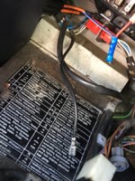 Double black wire coming from harness at top left
2.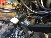 Round connector in the middle of the frame EDIT: Per HB Chris: The round connector under the dash is backup lights.
3.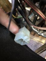 Multi pin under the steering column. EDIT: This turned out to be part of the Automatic gear selection display on the dashboard.
4.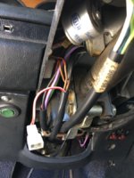 Possibly seat buzzer to be connected to relay at top of pic? EDIT: Per Stevehose: Yes that is it.
5.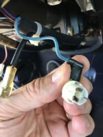 Strange connector under steering column close to steering wheel. I believe the wire on the left goes to horn pin. EDIT: Per Stevehose: Light for the prisma.
I have several wires which are dangling unconnected to anything under the steering column and around the fuse box area. The strange part is that a few of them are multi pin connectors with seemingly no matching male or female plug anywhere... Do any of these jump out at you as being an obvious one? This is a US '74, previously automatic. Two modifications have been made that I know of: a previous owner installed a stereo in the 80's, and the car was converted to 5 speed/Motronic 1.3. I would like to get rid of all of the stereo wiring crap and return the wiring to as close to stock as possible.
1.
 Double black wire coming from harness at top left
2.
 Round connector in the middle of the frame EDIT: Per HB Chris: The round connector under the dash is backup lights.
3.
 Multi pin under the steering column. EDIT: This turned out to be part of the Automatic gear selection display on the dashboard.
4.
 Possibly seat buzzer to be connected to relay at top of pic? EDIT: Per Stevehose: Yes that is it.
5.
 Strange connector under steering column close to steering wheel. I believe the wire on the left goes to horn pin. EDIT: Per Stevehose: Light for the prisma.
Last edited:

