Question for members with Stahl headers

How so? It's still a ways from the tailpipe so leakage is not a factor.

Honestly I don’t know but I have never seen an O2 sensor that far down. Admittedly all of my previous cars had cats. The 02 sensor works by heating the element so I would think that you would want it closer to the combustion chamber versus underneath the parking brake lever.
 
I have seen pre-cat O2 sensors living down next to the trans. And post-cat sensors are behind the cat, even farther back. I assume the exhaust gasses must reach appropriate temps even at those locations.
 
i think the o2 sensor should sample gases from all cylinders. accordingly, my thought with the stahl headers is to either create a connector pipe in the two horizontal tubes before it enters the resonator ... and have the bung mounted in that. if the exhaust i end up using has a "y" connector to a single pipe, then i will have a bung put in the single pipe.
 
i think the o2 sensor should sample gases from all cylinders. accordingly, my thought with the stahl headers is to either create a connector pipe in the two horizontal tubes before it enters the resonator ... and have the bung mounted in that. if the exhaust i end up using has a "y" connector to a single pipe, then i will have a bung put in the single pipe.

The only issue with connecting the Stahls after the collector is that removal would be a PITA if they were welded together. Putting it on the muffler inputs would probably make life easier.
 
i don't intend to weld my stahl sections together ... or to the exhaust pipe. tack weld is one thing but one continuous pipe makes it difficult to remove. the stahl is easier to remove / install in pieces rather than all together.
 
The O2 sensor is heated by voltage, not the exhaust gas, yes? So it shouldn't matter where it is as long as fresh air isn't back flowing up to it?
 
The O2 sensor is heated by voltage, not the exhaust gas, yes? So it shouldn't matter where it is as long as fresh air isn't back flowing up to it?

Kind of right? The heating of an O2 sensor via voltage is to get it to operating temp. It is the heat of the exhaust gases is what creates voltage in the sensor, and the creation of said voltage is how you measure oxygen. That is how a narrow band O2 sensor works anyway.
 
That wooshing sound is the technology going right over my head! Doesnt the amount of oxygen create the resistance/voltage that is read by the computer, not the heat of the gas? I dunno.
 
That wooshing sound is the technology going right over my head! Doesnt the amount of oxygen create the resistance/voltage that is read by the computer, not the heat of the gas? I dunno.

Oh stop pretending like you know less about this voodoo than I do. :D Unfortunately I am educating myself on the process and thinking out loud at the same time. I think that there is a sweet spot for the sensor with respect to exhaust temps, but I don’t know where that is. The o2 changes do trigger the voltage change, which makes perfect sense in restrooms to. I think I got the part about the sensor creating the voltage, but it isn’t “the heat”.

This is pretty good:
https://www.ngkntk.co.uk/index.php/technical-centre/lambda-sensors/how-does-the-lambda-sensor-work/


At temperatures in excess of 300°C the zirconia element possesses a property that causes a transfer of oxygen ions. This movement creates a voltage. The greater the difference of oxygen concentration between the exhaust gas and the ambient reference air in the centre of sensor thimble the higher the voltage produced. The voltage produced in the fuel lean position should be approximately 0.1 volt and in the fuel rich position approximately 0.9 volt. The very useful part of this function is that at around the stoichiometric point there is a relatively large change in voltage. This allows the sensor to keep the engine emissions within strict limits by constantly bringing the fuelling system back from a fuel lean or fuel rich position to retain the stoichiometric mixture. The time taken to switch from fuel lean to fuel rich is approximately 300 milliseconds.
 
@Stevehose I just have to say thanks for the help on this. I am 90% theory and 10% application. The stuff that you talk about has been executed, by you. You have done more e9 work on your dining room table than I have done in my garage. I’ll try stop and listen every now and then. :D
 
all i know is that all of the o2 sensors that i have changed in the past were mounted in a pipe that was common to the entire exhaust system. but we all know my memory is perhaps not what it should be. and i make both of you appear to be closer to the knowledge of our friend SFDon than me.
 
so i presume you have 2 downpipes ... therefore my theory has been debunked and i don't need to worry about creating a connector between the 2 pipes before the resonator. COOL.
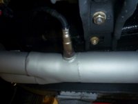
 
so i presume you have 2 downpipes ... therefore my theory has been debunked and i don't need to worry about creating a connector between the 2 pipes before the resonator. COOL.

I think that the vast majority of enthusiasts and OEM’s run a single sensor. It is either in one downpipe or in the collector. On my water cooled VW’s it was immediately in front of the cat, just after the collector. I don’t plan on making an H pipe. I will take what readings I can get from one sensor but give myself the ability to swap the sensor over to the other side (after the exhaust cools down).

Honestly I’m just not sure about a custom H pipe sensor location. Does that area get enough exhaust flow to produce an accurate and timely reading of what is happening? The thing that I do know for certain is that I do not want to weld my headers together. That just sounds like an installation nightmare to me.
 
FWIW I put two bungs on a vintage car with Dual carbs and dual exhaust. When fine tuning I dialed in one carb first then the second. This allowed me to do things like checking that the progression circuits were coming in the same way and idle mixture was right on.

For running I just monitor one side, if at all. The bungs were ahead of the center resonator where the two exhaust streams mix. Equivalent to ahead of the center resonator but aft of the header collector on an E9
 
Not sure if this is a dumb question or not, but: what is an H pipe (relative to our cars' exhaust path)? I believe the two down pipes connect to the double entry resonator on a stock set-up. And in a non-stock, higher flow center resonator type (ala Coupe King and what I currently plan on doing), the two secondaries get combined into one final pipe (also where I plan to locate the O2 sensor).
P1020455-9001.jpg
Picture is of the Coupe King exhaust set-up...
 
Not sure if this is a dumb question or not, but: what is an H pipe (relative to our cars' exhaust path)? I believe the two down pipes connect to the double entry resonator on a stock set-up. And in a non-stock, higher flow center resonator type (ala Coupe King and what I currently plan on doing), the two secondaries get combined into one final pipe (also where I plan to locate the O2 sensor).
View attachment 40379
Picture is of the Coupe King exhaust set-up...

Certainly not a dumb question. H pipes and X pipes are really common with domestic V8's. It is a pipe that connects one exhaust pipe to the other. The H pipes are basically a perpendicular pipe that joins the two together. Folks seem to suggest it is a good option for blended exhaust readings from all six cylinders (or 8 in a domestic). An X pipe is the same thing but flows a little better. Looking at the pic below, you have to wonder if the middle of the H gets appropriate flow for an O2 sensor. I think finding an OEM setup where the O2 sensor is placed there would put that question to bed. OEM's want to reduce emissions as much as possible, so the O2 sensor is placed in a spot that provides accurate readings.

c22a7b1fef416a465bc10b27b0d2df9e.jpg
 
H pipes and X pipes are really common with domestic V8's.
I am familiar with this in a V8 system, which would include a full/true dual exhaust all the way back. Didn't realize that folks were doing it with the e9, since the two down pipes join/combine in the first resonator anyway. Well, I guess if one wanted to add the "all 6" O2 sensor within an otherwise stock setup, this could be added between the two down pipes under the car (light bulb just went off as I typed it...). But I agree with you, that this wouldn't seem to get as accurate/complete of data for our purposes.?.
 
Back
Top