I’d been interested in it.
You are using an out of date browser. It may not display this or other websites correctly.
You should upgrade or use an alternative browser.
You should upgrade or use an alternative browser.
Gauging interest / A Dedicated Headlamp Harness with Fuses and Relays / Concept / Demand ?
- Thread starter paul cain
- Start date
Years ago, there was ban effort in the industry to move to 42 volts (the "12V" battery is actually 14 volts, so three of them in series makes 42 volts) https://www.powerelectronicsnews.com/whatever-happened-to-the-42-volt-bus/This design oversight is rather astonishing to me... as the high current problem has been known for more than a century...
Everyone has heard the formula: P = V * I = I^2 * R ... power is voltage times current or current squared times resistance.
Shortly after Thomas Edison invented the electric light bulb, he teamed up with Westinghouse to build out a set of DC-powered electric street lights (it was a PR stunt). The PR stunt went quite well, and the general public was blown away seeing electric lights replacing gas lamps for the first time.
But a clever mathematician named Charles Steinmetz knew the team was headed towards disaster. Steinmetz understood the ohmic loss problem the nascent power industry would be facing... and thus argued for the superiority of AC power over DC power.
That is why long-haul power distribution is done at the 600KV or 1MV level ... P = V * I... if V is very large, I can be very small.. yet the equivalent amount of power is transferred via transformers and transmission lines. AC power enables the use of transformers.. P = V1 * I1 = V2 * I2
Obviously, we don't have AC power distribution inside a car, hence the use of relays for high power circuits. Relay control circuits require fairly minimal power and can be implemented with small gauge wire, reducing cable weight & cost. The relay contact side of the circuit - high power - requires large gauge wire to handle the current flow and can be in a localized area.. such as the headlight harness in this thread.
And in a strange twist, P = V * I keeps rearing it's head... as electrical demands in cars grew.. manufacturers were finally forced to switch from 6V to 12V systems.. My mom & dad owned a '67 Wolfsburg VW.. the year VW made the 6 to 12V transition.... And Tesla's cybertruck is the chief driver behind the latest transition..
P = V * I
or
P = 4*V * 1/4*I
Yes... if you jump from a 12V battery to a 48V battery, you can scale down the DC current by a factor of 1/4. And a 48V battery is low enough voltage you won't shock the piss out of individuals who accidentally short themselves across hot & ground leads. (Incidentally, 48V powered the old POTS telephone service before cell phones left landlines in the dustbin of history.)
In an electric car that has to deliver hundreds or thousands of peak amps to electric motors.. scaling down the current by 1/4 allows you to use significantly thinner copper wire.. and that leads to a significant reduction in cost and weight.
I wholeheartedly support this upgrade if properly constructed. Racecars utilize kill switches and relays for safety.. you don't want heavy gauge, high current electrical wiring criss-crossing the vehicle. In the event of a crash and severed wires... nobody wants a severed, high-current wire (400A for starter motors) near them. You want the entire electrical system shutdown. The E9 fire image posted by ErikNetherlands is very real. (Same for poorly wired Corvettes and fiberglass bodies.)
Apologies for the rant, but the electrical engineer in me couldn't resist.
This ultimately didn't go anywhere because the difficulty of changing was just too great
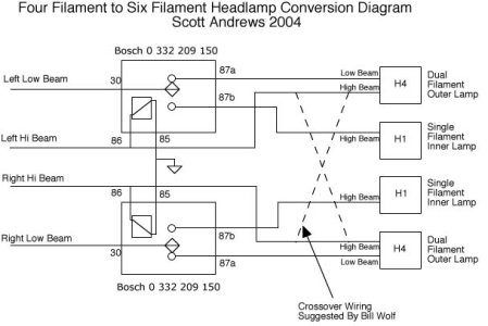
I rewired my 635 headlamps using a pair of relays in order to use dual filament outer lamps. What this six filament system did was to feed current to the low beam outer filaments in the low beam mode, and then to energize the high intensity outer filaments and the inner low beams in the high beam mode. SO the inner lamps came on to fill in the front region in the high beam mode, but at any given time only one of the outer filaments was energized. Worked great, and it relied on the relay controlled power for the headlamps (standard inthe 635).
Here is the circuit I developed.
That said, I'd definitely be interested in a professionally made improved E9 headlamp harness.
Here is the circuit I developed.
That said, I'd definitely be interested in a professionally made improved E9 headlamp harness.
Attachments
I also second the idea of a power window control unit.
The windows seem to be a chronic issue on these cars. Routing a fused 12 volt line to each motor and using a relay located at the motor would add some wiring, but it would assure adequate current to the motors, and it would also reduce the current in the flimsy window switches in the console. I suppose a really slick solution would be to just route 12 volts to each window motor and use a Bluetooth controller in the console to send signals to each motor controller. That would eliminate some wiring! Not very period correct though. The other approach would be to use a LIN controller that superimposed the window commands on the 12 volt window current line. Then use the console switches to tell the master LIN controller which window to control. Probably the most difficult part of that would be to handle arbitration, so the system would not get confused if two switches were activated at the same time.
The windows seem to be a chronic issue on these cars. Routing a fused 12 volt line to each motor and using a relay located at the motor would add some wiring, but it would assure adequate current to the motors, and it would also reduce the current in the flimsy window switches in the console. I suppose a really slick solution would be to just route 12 volts to each window motor and use a Bluetooth controller in the console to send signals to each motor controller. That would eliminate some wiring! Not very period correct though. The other approach would be to use a LIN controller that superimposed the window commands on the 12 volt window current line. Then use the console switches to tell the master LIN controller which window to control. Probably the most difficult part of that would be to handle arbitration, so the system would not get confused if two switches were activated at the same time.
jmackro
Well-Known Member
Man, you're really complicating this problem! There are already wires running from the console switches to the door and rear seat area. Yes, those wires and the switches are undersized for carrying the full current of the motors, but despite any corrosion on their connectors, they can easily deliver the few milliamps that the relays draw. So the problem of sending the "UP-DN" signal to the motors is solved.I suppose a really slick solution would be to just route 12 volts to each window motor and use a Bluetooth controller in the console to send signals to each motor controller. That would eliminate some wiring! Not very period correct though. The other approach would be to use a LIN controller that superimposed the window commands on the 12 volt window current line. Then use the console switches to tell the master LIN controller which window to control. Probably the most difficult part of that would be to handle arbitration, so the system would not get confused if two switches were activated at the same time.
If you want to go high tech, I suppose that solid state relays would be more 21st Century than the old click-clack type. But unless you go through a lot of toll booths, you are unlikely to wear out a mechanical window relay in your lifetime.
I read it four times and I got lost five...I rewired my 635 headlamps using a pair of relays in order to use dual filament outer lamps. What this six filament system did was to feed current to the low beam outer filaments in the low beam mode, and then to energize the high intensity outer filaments and the inner low beams in the high beam mode. SO the inner lamps came on to fill in the front region in the high beam mode, but at any given time only one of the outer filaments was energized. Worked great, and it relied on the relay controlled power for the headlamps (standard inthe 635).
Yeah, my thought here was to avoid adding an extra power wire to each motor. I suppose the easiest solution would be to simply locate the window relays in the console and use the existing wiring. The wires are not really the limiting factor. it is ultimately, IMO, the switches. OTOH, you could run a larger power wire out to each motor, locate a relay there, and control it using the existing wiring.. Sort of a heavy handed solution, but that would assure adequate power to the motors.Man, you're really complicating this problem! There are already wires running from the console switches to the door and rear seat area. Yes, those wires and the switches are undersized for carrying the full current of the motors, but despite any corrosion on their connectors, they can easily deliver the few milliamps that the relays draw. So the problem of sending the "UP-DN" signal to the motors is solved.
If you want to go high tech, I suppose that solid state relays would be more 21st Century than the old click-clack type. But unless you go through a lot of toll booths, you are unlikely to wear out a mechanical window relay in your lifetime.
you don't have to run 4 complete runs from the battery to each motor - you need 1 major run into the car from the battery and distribute it to each of the 4 motors. my thought was to use the existing wiring + switches to power the relay to control the motors. this is also diagrammed in the FAQ - https://e9coupe.com/forum/threads/e9-parts-dimensions-drawings-technical-info-and-models.43743/ ... thread 8. now this is a drawing just for the sardine motors.
Yeah, I could have been clearer on that.I read it four times and I got lost five...
The issue has to do with using four filaments vs six. The four filament setup has the high beams on the outside of the four lamp set, and the low beams on the inside. I believe the idea is that when the high beams are on the inner low beams are also on, but when the high beams are off, the only low beam lamps are in the inner spaces, which not only looks weird, it doesn't do a very good job of lighting the edges of the road.
The six filament setup has a low beam filament in each lamp, and the high beam filament in the outer lamps (so the outer lamp has two filaments, high and low). This gives you three lighting options:
1) High Beam: Outer high beam filaments on, inner low beam filaments on; Low Beam: Outer low beam filaments on, out high beam filaments off, inner low beam filaments off. This is the setup my relay circuit provides.
2) High Beam: High and Low beam outer filaments on (heats up the outer lamps a LOT), inner low beam filaments off. Low Beam, all four low beam filaments on.
3) High Beam: Outer High Beam filaments on, All Low beam filaments off. Low Beam: High beam filaments off, all four low beam filaments on. (not as complete lighting in high beam, and excessive lighting in low beam).
So the circuit I posted sets up the six filaments in configuration 1 above.
I am certainly not the expert here, nor the Stern!FYI - Paul is an expert engineer focused for decades on automotive applications.
Follow the leader….
I can’t imagine driving a coupe without a fuse and a relay in the low beam circuit.
Every car leaving the shop gets upgraded headlight wiring.
It’s easy, cheap and effective.
Besides keeping the rest of the wiring in the front loom safer- the addition of a relay right by the battery provides a huge boost in low beam light.
Voltage drop over distance is terrible for lighting..
Good reading from Daniel Stern:
Why Bother With Relays?
Power for the headlights is controlled by (wait for it) the headlight switch. In almost all vehicles built through the late '90s, and quite a few built after that timeframe, all headlamp current runs through the switch. That is: long lengths of thin wire to and from the switch, which contains tiny contacts. All of this adds up to a surprising amount of resistive voltage drop, which takes a big bite out of headlamp output.
In many cases, the thin factory wires are inadequate even for the standard original-equipment headlamps. There's a large element of automaker cost-cutting involved; it might sound like a joke to say they figure headlamps are only used at night, so that's a 50% usage duty, so they cut the wire gauge in half, but it's actually pretty close to how these kinds of decisions are often made in the auto industry where just about every last fraction of a cent that can be shaved from the build cost, will be.
And science has yet to give us the wiring, connections, and switch contacts that improve with age; in fact they do the opposite.
Headlamp bulb light output is severely compromised with decreased voltage. The drop in light output is not linear, it is exponential to the power 3.4. For example, let's consider a bulb with a rated output of 1000 lumens at 12.8 Volts and look what happens when it is operated at different voltages:
10.5V : 510 lumens
11.0V : 597 lumens
11.5V : 695 lumens
12.0V : 803 lumens
12.5V : 923 lumens
12.8V : 1000 lumens ←Rated output voltage
13.0V : 1054 lumens
13.5V : 1198 lumens
14.0V : 1356 lumens ←Rated life voltage
14.5V : 1528 lumens
(Outside North America bulb output and lifespan are both rated at 13.2v, but the effect of voltage drop is the same).
When operating voltage drops to 95 percent (12.54v), headlamp bulbs produce only 83 percent of their rated light output. When voltage drops to 90 percent (11.88v), bulb output is only 67 percent of what it should be. And when voltage drops to 85 percent (11.22v), bulb output is a paltry 53 percent of normal! It is quite common for factory headlamp circuits to produce this kind of voltage drop, especially once they're no longer brand new and the connections have accumulated some corrosion and dirt.
") I am simply the fire starter. You folks are off with some excellent replies on this topic.
I am simply the fire starter. You folks are off with some excellent replies on this topic. The expert here is Galahad.
I am confident he is taking in all your suggestions and schematics. Lets please stay focused on the topic of protecting and improving the headlamp circuit (redesigning the window lift motors is a more complicated and separate topic -ask me how I know.) I encourage one of you to start a dedicated thread on window lift motors.
For the redesigned headlamp wiring there should be some elegant, modern solutions. Ample amps (sorry) are available at the + side on the battery, white and yellow wires for the high and low beam are inches away from the battery. I for one would want to do a short run with a heavy gauge wire off the battery + and into this new relay and fuse box, then new (heavier than OEM gauge) wiring out to each headlamp, with (4) new 3 pin mating connectors. One solution would be to repurpose your old hi and low beam wiring with the 3 pin connectors and plug them straight into the new box as the low current trigger for the new relays. Then use fresh wiring out to the four bulbs. Last item, add a really beefy ground circuit. My two cents -gents.
Yeah, that's probably the simplest way to do it. The battery line would need to split somewhere in the instrument panel, and run to the doors and to the rear sides. Since all windows are seldom activated at the same time, the single B+ wire only needs to be large enough to support one motor with some margin.you don't have to run 4 complete runs from the battery to each motor - you need 1 major run into the car from the battery and distribute it to each of the 4 motors. my thought was to use the existing wiring + switches to power the relay to control the motors. this is also diagrammed in the FAQ - https://e9coupe.com/forum/threads/e9-parts-dimensions-drawings-technical-info-and-models.43743/ ... thread 8. now this is a drawing just for the sardine motors.
That said, it might be fun to figure out how to modernize the electric windows, since they are all in all pretty awful.
1) Larger motors with more direct current sourcing (the discussion we have been having).
2) Auto up/down, with auto stop by reversing the switch momentarily
3) Auto Stop at top and bottom
4) Anti pinch
2-4 require some level of processing and some sort of sensors. Most car window systems use motor stall current to sense a pinch. They either have position sensors to sense top and bottom, or they use stall current for that too. If they have position sensors, then they can differentiate between a top/bottom stop and a pinch, so then the pinch automatically backs off the window a bit, whereas top/bottom just stops. I would do this by placing a sensor/controller at each motor, and then using a LIN network to send up/down commands to the window controllers. Basically pressing "up" would start the window up, and it would just keep going up until it stopped at the top, or there was a short "down" signal, which would indicate a stop. A second "down" signal would then send the window down...Same thing in reverse for down. Pretty simple state machine, easy to implement in a PIC microcontroller, which can be found with a LIN interface.. so basically a one chip and one relay module for each window.
All very interesting, but I am not sure I want to depart "too" much from the original...
Yeah, this is basically what I ended up with on the 635. The relays are right next to the battery on the left front of the engine bay. Mine was hand made, but a nice well structured controller (thinking something with relay sockets to avoid a bunch of spade connectors to the relays), and crisp new wiring would be a huge improvement. Even on a 1980 car the wires were pretty crusty!I am certainly not the expert here, nor the Stern!
The expert here is Galahad.
I am confident he is taking in all your suggestions and schematics. Lets please stay focused on the topic of protecting and improving the headlamp circuit (redesigning the window lift motors is a more complicated and separate topic -ask me how I know.) I encourage one of you to start a dedicated thread on window lift motors.
For the redesigned headlamp wiring there should be some elegant, modern solutions. Ample amps (sorry) are available at the + side on the battery, white and yellow wires for the high and low beam are inches away from the battery. I for one would want to do a short run with a heavy gauge wire off the battery + and into this new relay and fuse box, then new (heavier than OEM gauge) wiring out to each headlamp, with (4) new 3 pin mating connectors. One solution would be to repurpose your old hi and low beam wiring with the 3 pin connectors and plug them straight into the new box as the low current trigger for the new relays. Then use fresh wiring out to the four bulbs. Last item, add a really beefy ground circuit. My two cents -gents.
The key question is what is the filament configuration (see my post #29 above)...