I'm traveling at the moment but when I'm back at home this weekend I'll set it up and take a bunch of photos. I'll probably post it as a separate thread since I suspect that others might be interested in how it can be done. Up until they released this crossbeam earlier this year the only option would have been as you have it, which again, is what QJ would likely tell you to do, but may be less ideal for our cars. The crossbeam comes with its own set of pucks and since you are lifting directly on the large frame portion you can use standard rectangular pucks and don't need the pinch weld ones. The only downside is that there is a portion that crosses the car on its underside at about the end of the bell housing, so if you were planning on doing work involving removing the transmission then you would use standard jack stands for that. The pictures below are of the car on the stands with the crossbeam, which you can see in the view looking down into the engine bay.I have the normal rectangle "pucks" and the pucks for pinch welds (they have a cross cut into them). Where do you set yours up and which puck do you use?
You are using an out of date browser. It may not display this or other websites correctly.
You should upgrade or use an alternative browser.
You should upgrade or use an alternative browser.
1972 Bavaria - Full build and swap
- Thread starter e30strube
- Start date
e30strube
Well-Known Member
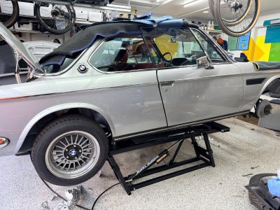
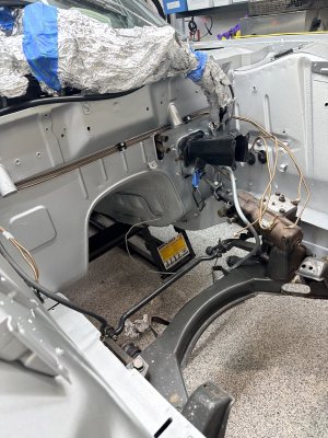
I'm traveling at the moment but when I'm back at home this weekend I'll set it up and take a bunch of photos. I'll probably post it as a separate thread since I suspect that others might be interested in how it can be done. Up until they released this crossbeam earlier this year the only option would have been as you have it, which again, is what QJ would likely tell you to do, but may be less ideal for our cars. The crossbeam comes with its own set of pucks and since you are lifting directly on the large frame portion you can use standard rectangular pucks and don't need the pinch weld ones. The only downside is that there is a portion that crosses the car on its underside at about the end of the bell housing, so if you were planning on doing work involving removing the transmission then you would use standard jack stands for that. The pictures below are of the car on the stands with the crossbeam, which you can see in the view looking down into the engine bay.
I've seen people use the QJ sideways also and that always seemed weird. I guess if you were doing suspension or brake work, it wouldn't matter. I didn't know they made the cross bar... I'll check it out. Which QJ unit are you using?
@StephenZ generally the Quick Jack works really well. Once you get the feel of where to line it up on the car, it's easy to get it back in the same spot. They have different units with various lengths and weight capacities, so depending on which car or cars you want to lift, you would have to see what fits. They are also heavy. You have to manhandle them a bit to move around. I have the wall mounts and they really help keep things out of the way when not in use. They definitely get higher than a standard jack and jack stands.
Yes I have tried to sideways and agree it seems weird. I also agree that they are really easy to use overall. The crossbeam does make it a little bit of an extra step but it’s still way easier than using four separate jack stands. I have the 7000 but mainly because I wanted it to lift my pickup. Previously had a 5000 which worked great. Often can find these on marketplace and I agree heavy but moveable. I installed casters on mine and tend to keep them slammed together underneath the car, can just drive in and out of the garage over them, even in my little MG
Great info, guys. Thanks! That crossbeam is new to me, too. Interesting. I’ve heard of the sideways, too, and yeah, seems like it would be freaky..but makes sense as to why it would work fine.
It would be so nice to be able to lift the car up a bit easier without having to get a whole two post lift..
It would be so nice to be able to lift the car up a bit easier without having to get a whole two post lift..
I'll post a full thread on the quickjack, but @e30strube I'll post this picture here of the underside of my car that I discovered while changing the fuel lines today. As you can see, one edge of a non-supporting piece of metal had been bent down, likely by someone jacking the car incorrectly. It pressed up against but didn't crush the fuel lines. That's the danger with using the pinch weld on our cars - the fuel lines run RIGHT next to the weld. See my new post for full details of the QJ with the crossbeam.

Oh wow. Yeah, I have my lines off at the moment and will be watching that carefully on install. The pinch welds can definitely become 'weapons grade' with a bad squish..
Let me know if you want any cunifer copper tubing for those lines. I have a bunch left over and happy to send it your way for not much
I appreciate that! Surprisingly, my lines are basically perfect...I think being a cali car that was never really messed with over the years, left most everything in pretty nice condition. The copper is super easy to shape, though, right?Let me know if you want any cunifer copper tubing for those lines. I have a bunch left over and happy to send it your way for not much
Yes it shapes easily and doesn’t crease as much when you bend it.
e30strube
Well-Known Member
I'm not sure if it's still available, but about 2 years ago, you could still buy the fuel line from BMW. It comes bent in half, but the rest of it actually conforms to the shape it needs to be. The cunifer/Nickel Copper line is really easy to bend and flare. I have a combo of AN and standard flare lines used throughout the car.
I looked and that fuel line isn’t available anymore. I also talked to Don who confirmed that it’s NLA
Great build, great skill set and a SICK amount of work.
@e30strube what did you use to recover the under panels under the dash and steering column?Getting the interior back together. Recovered the center console side panels and the under dash pieces. The rear seat area was used to house the stereo amp and the battery as seen before. Given age, I had to rebuild the under steering wheel panel and the rear shelf.
View attachment 218349
View attachment 218350
View attachment 218351
View attachment 218352
View attachment 218353
View attachment 218354
View attachment 218355
View attachment 218356
e30strube
Well-Known Member
@Paulaner Black vinyl.
The center console pieces are just wood, so they're easy to modify. The glovebox is a weird spongy material glued to plastic. Then the driver side pieces are MDF. I just prepped them and had a local auto upholstery place wrap them in the vinyl. The steering column is metal and I repainted it.
The center console pieces are just wood, so they're easy to modify. The glovebox is a weird spongy material glued to plastic. Then the driver side pieces are MDF. I just prepped them and had a local auto upholstery place wrap them in the vinyl. The steering column is metal and I repainted it.
e30strube
Well-Known Member
e30strube
Well-Known Member
ITB installation... something I wanted to do from the beginning, but didn't get to. Not pictured is the hours of tuning to get the car to run correctly up to this point... and the conversations with both Drew and Don from the boards here.

Intake manifold removal and wire labeling...

Test fitting the RHD Engineering kit

Had everything ceramic coated black... getting the vacuum connections installed.

Installing the throttles...

Fuel rail on... went through 3 fittings for the fuel line... also installed the new fuel pressure regulator on the fender. Had to make new fuel lines from the fender well to the regulator. Also had to install a shorter throttle cable... I believe from an early E30.

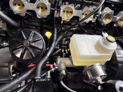
Vacuum block that allows for the connection to the brake booster, fuel pressure regulator, ECU, and throttles. I made a small bracket to mount this to the motor mount. I also kept the stock idle control valve at the bottom of the picture.

Intake manifold removal and wire labeling...
Test fitting the RHD Engineering kit
Had everything ceramic coated black... getting the vacuum connections installed.
Installing the throttles...
Fuel rail on... went through 3 fittings for the fuel line... also installed the new fuel pressure regulator on the fender. Had to make new fuel lines from the fender well to the regulator. Also had to install a shorter throttle cable... I believe from an early E30.
Vacuum block that allows for the connection to the brake booster, fuel pressure regulator, ECU, and throttles. I made a small bracket to mount this to the motor mount. I also kept the stock idle control valve at the bottom of the picture.
e30strube
Well-Known Member
That is glorious
rblongboarder
Well-Known Member
Let me make sure I understand your build...
1. You removed the M30B35 style intake manifold with the single throttle body and air flow sensor (MAF?)
2. You replaced the intake manifold with individual throttle bodies (ITB's) that control airflow... drive by cable..
3. You still have a fuel rail, with ECU-controlled EFI injectors..
How do you get ITB throttle position into the ECU? There has to be a position sensor somewhere.. because your original cold air intake had a sensor, I think. I believe I can see it in one of these photos:
Hood modifications... some of this was due to the removal of the latch mechanism. I used Quick Latch hood "pins" and mounted them to plates at the strut tower. They function via a push button release and are relatively simple looking. I also added hood struts on brackets I made for both the hood and the body. These were loosely based on someone else's post I found here on the boards. These are stainless steel units from McMaster Carr. For the hood insulation, I made templates with tape and poster board and then cut Design Engineering Inc. sheet insulation to fit. It's sticky on oneside and...

e30strube
Well-Known Member
@rblongboarder I run Megasquirt as my ECU. It replaces the original MAF, but requires the addition of a Throttle Position Sensor, Intake Air Temp Sensor, and a MAP sensor that is built into it. I originally used the factory M30B35 intake manifold, but most (especially with E9s) seem to use an older variant of the intake manifold. The TPS is mounted to the throttle body (mine is from an E36). The factory intake manifold has a single throttle body, so it is pretty simple.
When switching to the ITBs, there is a linkage that connects all of them together... or better stated, it has three pairs that are tied together via adjustable linkages. The TPS now sits at the end of that assembly and is able to send % open/closed amounts to the ECU. I had to update to Alpha-N which bases fuel load on TPS % and RPM, instead of the more common RPM and Engine Load / Vacuum. With no plenum, there isn't enough vacuum for the MAP sensor to read what's happening. There are downsides to this, but the engine actually still runs smoothly. The vacuum block in my picture helps to tie the small amount of vacuum being generated together, so that a reading can be had and you can still "power" things that need vacuum... like the power booster, sensors, etc.
I also now run a catch can that I tied into the valve cover and the Idle Control Valve. The normal connection from the valve cover to the intake manifold is no longer possible.