That is some very impressive CAD work there. What software do you use? I use Fusion 360 but I'm a hack.
It's done in Fusion 360. I started using it about 6 months ago. There are a lot of YouTube video tutorials on it.
The core concept is to understand the difference between a "sketch", and the various solid operations.
Every sketch is done on a plane (those orange squares in the image above). You can use the existing XY, XZ, or YZ planes, or you can construct a plane using the "Construct" menu selection. That allows you to create offset planes (parallel to the basic planes), planes at an angle, etc. You can also create a plane by simply clicking an existing surface on the solid. When you click on the sketch menu in the upper left, you then select a plane for the sketch (or it automatically uses then you selected before doing the sketch menu. You then sketch the shape you want to create. To convert that shape to a solid you use the "extrude" or "create" menus. When the sketch has a closed form (all of the lines end on the form), you can selected the form and then extrude it perpendicular to the surface. Extrudes can be part of the body that the sketch was on (a "Join"), or a separate body ("New Body), or a "Cut" (*essentially a negative extrusion). You can specify the depth or height of the extrude, and you can also change from the default perpendicular extrusion to any arbitrary angle. There are other solid commands under the "create" menu. For example, if you go to the thread on the AC Condensate drain, I have been developing a replacement drain grommet for the AC evaporator. In that thread I showed an example of sketching a cross-section of the part, and then I created the part by selecting the "Revolve" operation in the "Create" menu, and then selected the cross section form, and the revolve axis. Fusion then rotated the form around the axis to create the part. It has a groove on one side. so I selected the top surface as my sketch plane and then drew a rectangle. I then extruded that rectangle downward as a "cut", and that was that... Took about 10 minutes, and most of that was getting the dimensions right.
In the speaker baffle above, I started with the base plate, extruded that up to create a solid plate, 5mm thick. I then sketched the shape of the oval on top of the upper surface of the plate, added the square speaker bases, and then removed all the interior lines to create a form that had the oval edges and the square corners. I then extruded that up another 5 mm to get that weird shaped fill section. I then sketched the same speaker mount rectangles on top of that surface. The tricky sloped mounts were done by creating a sloped plane that intersected the center of the top of the weird shaped surface. That plane was angled 5 degrees up. I sketched the speaker mount on that plane. Then the super trick was to do a "loft" command (under the "create" menu. Loft creates a morphed shape between two forms. So I selected the speaker mount form on the top of the weird shaped extrusion, and the speaker mount form on the angled plane, and poof! Fusion created the sloped solid between them. I repeated that with another plane angled the other way to get the other mount. And then I sketched holes and such and extruded them using the "Hole" command.
All those nice curved edges are done using the "fillet" command under the "modify" menu.
It sounds complicated, but it is really just matter of understanding the planes and sketches and how those relate to solid forms.
In my restoration thread "
72 3.0 CS 2240344 Restoration" I did an intake manifold for my triple Weber conversion. THAT was pretty complicated...



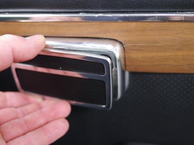
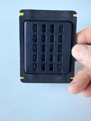
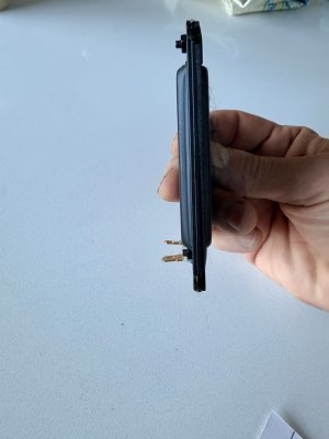
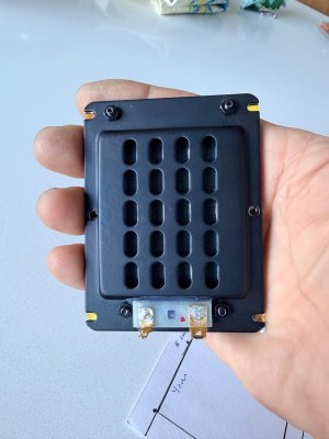
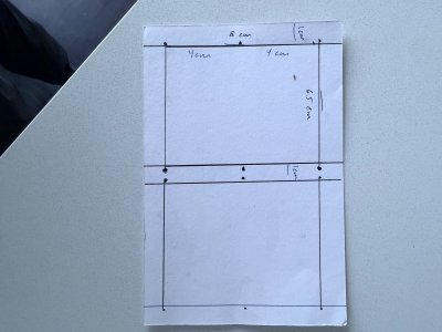
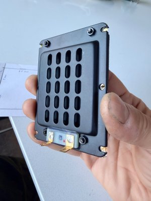
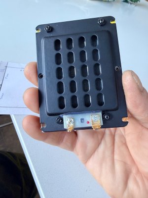
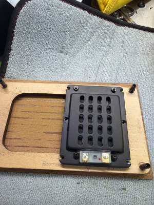
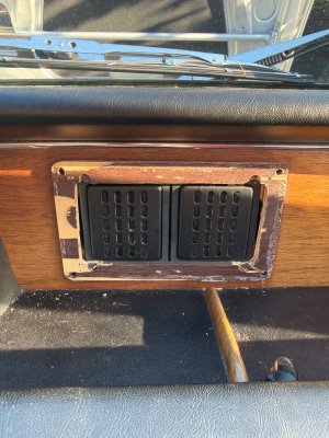
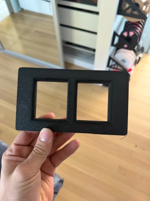
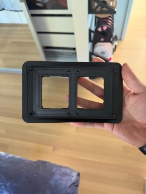
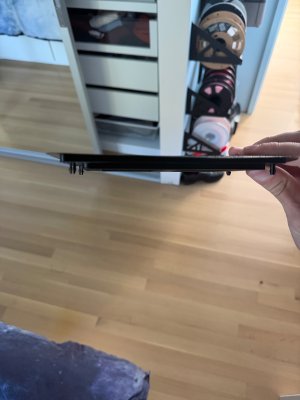
 ) would need to make for the planar speaker option.