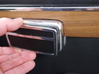
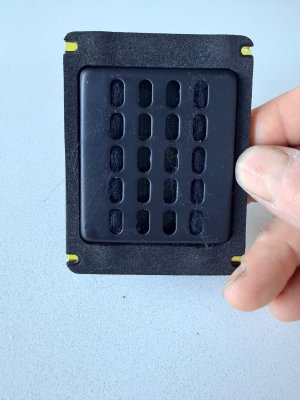
Front speakers

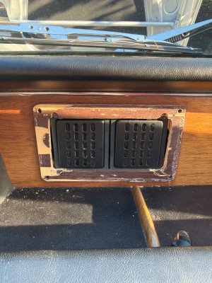
Is that something you’re making to install two smaller 2 1/2” speakers? Looks nice! I may just in the meantime fashion something out of sheet metal as a frame - since they are rectangular something shaped like a sideways digital 8 should work
With the planars they have fairly good horizontal dispersion so I think I’ll be ok having them flat mounted rather than slightly angled outwards - not sure it would get me much but I’ll play around with it
 
Is that something you’re making to install two smaller 2 1/2” speakers? Looks nice! I may just in the meantime fashion something out of sheet metal as a frame - since they are rectangular something shaped like a sideways digital 8 should work
With the planars they have fairly good horizontal dispersion so I think I’ll be ok having them flat mounted rather than slightly angled outwards - not sure it would get me much but I’ll play around with it
Yeah, doing it for Don. What is the mounting hole spacing and size on yours? I'd like to try them too. I am a bit concerned about the fit of the small speakers I designed these around. The back side is pretty bulky.

Screenshot 2026-07-04 at 2.51.48 PM.png
 
but i eventually settled on speakers down in the footwell with tweeters in the door ashtrays
 

Attachments

  • bmw e9 - ashtray tweeter 4.jpg
    bmw e9 - ashtray tweeter 4.jpg
    82.7 KB · Views: 24
JC, Here is a version of the baffle designed for your speakers.

This approach requires separating the back of the grille from the front, and then replacing it with this part (with grille cloth sandwiched in between).
Screenshot 2026-07-04 at 4.36.48 PM.png


Screenshot 2026-07-04 at 4.37.10 PM.png
 
JC, Here is a version of the baffle designed for your speakers.

This approach requires separating the back of the grille from the front, and then replacing it with this part (with grille cloth sandwiched in between). View attachment 221825

View attachment 221827
Ooh that looks nice. So I would peel apart the front wooden grill and then mount the speakers to this frame and then mount the wooden grill in front. I like it! Any chance you have that as a file that I can slice for 3-d printing?
Here is what I had roughed up, I was going to cut out some strips from sheet metal and practice with my new MiG welder, but your approach is far easier I think.
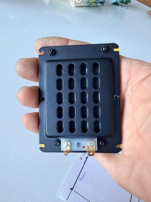
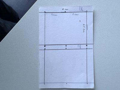
I’m attaching a schematic of what I had, the holes for the screws are 6.5 cm apart on the top and then 8 cm apart top to bottom with a middle one at 4 cm
 

Attachments

  • IMG_9713.jpeg
    IMG_9713.jpeg
    512.9 KB · Views: 14
  • IMG_9714.jpeg
    IMG_9714.jpeg
    379.6 KB · Views: 14
  • IMG_9716.jpeg
    IMG_9716.jpeg
    416.3 KB · Views: 15
  • IMG_9717.jpeg
    IMG_9717.jpeg
    501.3 KB · Views: 16
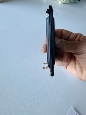
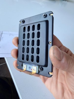
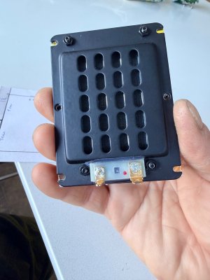
Also including a better picture of the back - across the top and bottom the cross beam can’t be as thick because there are some securing screws on the top and then the electrical connections at the bottom.
I like that we are coming up with some novel solutions - the alpine speaker worked fine, but was mono only and essentially a single channel (right or left) because blending them started to get a little wonky. Also had the issue of poking out just a bit too far. These aren’t cheap ($85 each) but they are quite solid, very low profile and seem as if they will work well. What is ever cheap with these cars?


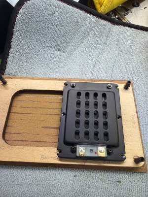
Update - ok, sometimes I think I’m dumber than I think I am. Looking at the backside of the grill, I may just route out a little bit more along the edges to mimic what you created above. It needs about 0.5 cm wider on each side. That’s an easy job and shouldn’t affect the structural part so that if I ever want to revert to original, no harm done
 

Attachments

  • IMG_9718.jpeg
    IMG_9718.jpeg
    358.5 KB · Views: 15
  • IMG_9719.jpeg
    IMG_9719.jpeg
    389.9 KB · Views: 13
  • image.jpg
    image.jpg
    886 KB · Views: 34
Last edited:
Sorry for the repeated posts, didn’t think it would actually get done so easily in the end. Here is picture before I glue the front panel back on. The only issue is that the original grill and wooden frame is fairly light so holds in place. My retaining pins are a bit old and with the added weight this will fall forward with any forward momentum. I can try to replace those pins, or more likely I’ll just stick a dab of earthquake putty (you guys in California know what that is) in each corner on the inside just to provide a little bit of extra holding power
 

Attachments

  • image.jpg
    image.jpg
    785.8 KB · Views: 37
Ooh that looks nice. So I would peel apart the front wooden grill and then mount the speakers to this frame and then mount the wooden grill in front. I like it! Any chance you have that as a file that I can slice for 3-d printing?
Here is what I had roughed up, I was going to cut out some strips from sheet metal and practice with my new MiG welder, but your approach is far easier I think.
I’m attaching a schematic of what I had, the holes for the screws are 6.5 cm apart on the top and then 8 cm apart top to bottom with a middle one at 4 cm
I'll be happy to send a .stl file that you can slice, or send out for printing. I sent mine to Xometry.com. They are printing it in SOLID ABS, as opposed to a light filled plastic. That will help with vibration, and also you can design it with tapped holes for attaching the speakers from the rear.

What is the space between the holes? Your diagram shows 65 mm, but according to the web site, the entire speaker flange is 67 mm, so the 65mm
Screenshot 2026-07-05 at 1.12.15 PM.png
seems somewhat too wide. Can you measure the following dimensions (they don't list much on the site).

Can you measure your speakers and provide dimensions for this drawing?
 
Last edited:
Ah you beat me to it - was about to go measure. Well, yes, looks good. I ended up just routing out the wooden piece since once I had peeled it off (which I would have to do anyways) it was somewhat useless to me and I had it in hand. But if you have the stl file send it along and I can print it and confirm it works so that others could go that route instead of having to use a router. Easier your way. The only permanent modification necessary to the car is that in order for any of these to fit, you do need to slightly enlarge the oval opening and make it more rectangular. I already needed to modify my “mounting” area for the Alpine to recess the attachment points. Once I install this pair, however, they are there with the car forever, and with today’s technology if someone wanted to go back to a single speaker or to use your Don-motivated dual-round-speaker option you’d print out the back half of the grill like you have above. I’ll direct message you my email address for the stl file. I have abs available
 
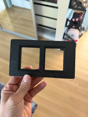
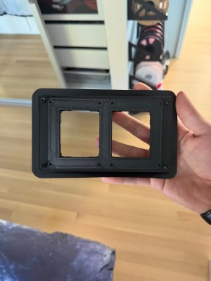
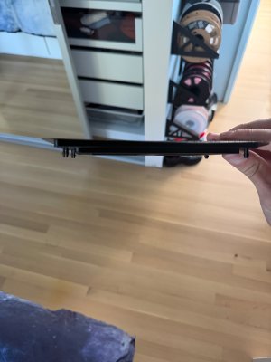
Here are the prints of the speaker holder for the planar speakers. I’m out of town on a 5-day cycling ride in Bend but will check the fit as soon as I get home. Pictures courtesy of my son. Nice job Scott!
 

Attachments

  • IMG_2927.jpeg
    IMG_2927.jpeg
    381.7 KB · Views: 15
  • IMG_2926.jpeg
    IMG_2926.jpeg
    366.4 KB · Views: 13
  • IMG_2925.jpeg
    IMG_2925.jpeg
    313.1 KB · Views: 15
OK, I took my old wood dash and modified it to fit the new speaker baffle. Itfits reasonably well, but i discovered several issues with it. First, the little pins are not very strong, and the tend to break off. I doubt they will actually hold the speaker assembly in place, since it is fairly heavy once the speakers are attached. The other thing I found was that the oval hole in the dash goes out to the edge of the grille recess at the top and bottom, and that area was open when the unit was inserted into the dash. You can sort of see this in the photo below. This is bad from a sealing perspective, since ideally we want the front and back of the baffle to be isolated from one another as much as possible.

IMG_6256.jpg

IMG_6257.jpg

IMG_6260.jpg


To address the mounting issue I added some screw holes from the front. These will engage new holes with blind nuts on the back side of the dash, and should secure the assembly in place. I then added simple holes that line up with the slots in the dash that the grille attaches to. I also added fillers to close up the spaces left by the oval hole. I made a second thin plate that has pins corresponding to the holes in the baffle and the dash. So the idea is that the thin plate gets covered with thin cloth, and glued to the back of the grille (which has been removed from the original grille backing plate). this assembly then fits onto the front of the dash, more or less the same as the original.

The last couple of pictures below show the two parts attached together (the "assembly" feature of Fusion is pretty slick!!)

You can see the baffle plate still needs a little tweaking so the cutout lines up better with the speaker holes.

Screenshot 2026-07-10 at 9.03.56 AM.png
Screenshot 2026-07-10 at 9.04.11 AM.png
Screenshot 2026-07-10 at 9.04.37 AM.png
Screenshot 2026-07-10 at 9.06.58 AM.png
Screenshot 2026-07-10 at 9.07.42 AM.png
 
Last edited:
That is some very impressive CAD work there. What software do you use? I use Fusion 360 but I'm a hack.
It's done in Fusion 360. I started using it about 6 months ago. There are a lot of YouTube video tutorials on it.

The core concept is to understand the difference between a "sketch", and the various solid operations.

Every sketch is done on a plane (those orange squares in the image above). You can use the existing XY, XZ, or YZ planes, or you can construct a plane using the "Construct" menu selection. That allows you to create offset planes (parallel to the basic planes), planes at an angle, etc. You can also create a plane by simply clicking an existing surface on the solid. When you click on the sketch menu in the upper left, you then select a plane for the sketch (or it automatically uses then you selected before doing the sketch menu. You then sketch the shape you want to create. To convert that shape to a solid you use the "extrude" or "create" menus. When the sketch has a closed form (all of the lines end on the form), you can selected the form and then extrude it perpendicular to the surface. Extrudes can be part of the body that the sketch was on (a "Join"), or a separate body ("New Body), or a "Cut" (*essentially a negative extrusion). You can specify the depth or height of the extrude, and you can also change from the default perpendicular extrusion to any arbitrary angle. There are other solid commands under the "create" menu. For example, if you go to the thread on the AC Condensate drain, I have been developing a replacement drain grommet for the AC evaporator. In that thread I showed an example of sketching a cross-section of the part, and then I created the part by selecting the "Revolve" operation in the "Create" menu, and then selected the cross section form, and the revolve axis. Fusion then rotated the form around the axis to create the part. It has a groove on one side. so I selected the top surface as my sketch plane and then drew a rectangle. I then extruded that rectangle downward as a "cut", and that was that... Took about 10 minutes, and most of that was getting the dimensions right.

In the speaker baffle above, I started with the base plate, extruded that up to create a solid plate, 5mm thick. I then sketched the shape of the oval on top of the upper surface of the plate, added the square speaker bases, and then removed all the interior lines to create a form that had the oval edges and the square corners. I then extruded that up another 5 mm to get that weird shaped fill section. I then sketched the same speaker mount rectangles on top of that surface. The tricky sloped mounts were done by creating a sloped plane that intersected the center of the top of the weird shaped surface. That plane was angled 5 degrees up. I sketched the speaker mount on that plane. Then the super trick was to do a "loft" command (under the "create" menu. Loft creates a morphed shape between two forms. So I selected the speaker mount form on the top of the weird shaped extrusion, and the speaker mount form on the angled plane, and poof! Fusion created the sloped solid between them. I repeated that with another plane angled the other way to get the other mount. And then I sketched holes and such and extruded them using the "Hole" command.

All those nice curved edges are done using the "fillet" command under the "modify" menu.

It sounds complicated, but it is really just matter of understanding the planes and sketches and how those relate to solid forms.

In my restoration thread "72 3.0 CS 2240344 Restoration" I did an intake manifold for my triple Weber conversion. THAT was pretty complicated...

 
Last edited:
Wow, amazing work and I’m impressed at how quick your turnaround is! Can’t wait to get home and see what modifications I (you :)) would need to make for the planar speaker option.
 
Back
Top