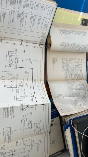
72 CSi wiring diagram

An addendum to my post above (now that I am sitting at my computer as opposed to composing this on my phone...)

Do you have a multimeter? Measures voltage, current and resistance (at a minimum). If not, go buy one. I recommend Fluke, but really any type will generally do.

For the lamp (or any other) terminal that causes the car to not run when you connect the wire, measure the component's terminal resistance to ground with the wire un-attached. If that resistance is less than about 6 ohms, then there is a short in that compomnent. It is not the wiring, it is the component you are connecting the wiring to.

It is highly unlikely that your wiring got compromised while out of the car unless you specifically changed it. It is possible that you may have cracked some insulation on re-install, but again unlikely. More likely is hooking things up wrong.

When I pulled the wires out of my car I labeled every wire as I disconnected it. Hopefully you did the same. If not get the Blue Book wiring diagram for your car, read the color, codes and connect things accordingly. If in doubt, trace the wire to its source (usually a fuse or a switch) to confirm what wire it is...

It is not mysterious, but it takes patience and attention to detail.

When I put the wiring back in my car I am going to label every single wire at both ends. If you want to do this get a wire lable maker.

Brady Wire Labeler
I'm with Scott on this one, although this is where the purist and the practical one diverge. Don (appropriately) told me there should only be black wires visible in the engine bay. He is right - my blue/striped wire that I added running to my additional temp gauge with a label saying "temp sensor" in yellow on it is not correct visually. But as a novice here, it sure is helpful to know when I'm on the other end of things in the fusebox and I see a wire labeled "temp sensor" to know what I"m looking at. Especially true for any circuits I added - between additional wiring for relays, wiring for three additional gauges, adding two additional aux wires long enough to reach the rear seat tucked into the recesses of the fusebox for any future upgrade, I'm trying to make sure that me and anyone after me knows what in the hell goes where.
I'll second Scott's suggestion on the multimeter. I'm still a novice there as well, but Rob Seigel's book "The Hack Mechanic Guide to European Electrical Systems" is really well written. He's a forum member here and I found the book helpful in understanding how the circuitry works.
 
completely agree on the only black wires visible. since i had my wiring harness completely open, i did my best to incorporate all new wiring into the newly taped harness and remove all of the unused ones. any new wiring going to new temp temp sensor or oil pressure sender runs thru black plastic tubing or is tape wrapped ... the black vinyl tubing runs over the top of the engine.
 
Last edited:
Yes perhaps my answer is to use some black plastic tubing to cover the wire and then for obvious things (temp sensor, for example) no need to have the end attached to the sensor labeled since it’s obvious, but label on the end in the distributor box area or fusebox area may be suitable and helpful without being tacky.
I know I can do a search, but any easy source for smaller diameter tubing for the wiring?
 
the nice thing about black vinyl tubing is that you can slide it over to see the color of the wires at a connector. all of the taped pieces have to leave a bit of the wire exposed so you know what goes where.

i buy smaller diameter tubing from Prancing Moose (Dave's Volvo page). should be listed in the FAQ - top sources. its hard to use tubing less than 3/16" to push a long piece of wire through. i found that i used a lot of 3/16" and a reasonable amount of 1/4" ... probably about 15' to 20' of 3/16" and 10' of 1/4". but i used it inside the car and trunk as well

 
An addendum to my post above (now that I am sitting at my computer as opposed to composing this on my phone...)

Do you have a multimeter? Measures voltage, current and resistance (at a minimum). If not, go buy one. I recommend Fluke, but really any type will generally do.

For the lamp (or any other) terminal that causes the car to not run when you connect the wire, measure the component's terminal resistance to ground with the wire un-attached. If that resistance is less than about 6 ohms, then there is a short in that compomnent. It is not the wiring, it is the component you are connecting the wiring to.

It is highly unlikely that your wiring got compromised while out of the car unless you specifically changed it. It is possible that you may have cracked some insulation on re-install, but again unlikely. More likely is hooking things up wrong.

When I pulled the wires out of my car I labeled every wire as I disconnected it. Hopefully you did the same. If not get the Blue Book wiring diagram for your car, read the color, codes and connect things accordingly. If in doubt, trace the wire to its source (usually a fuse or a switch) to confirm what wire it is...

It is not mysterious, but it takes patience and attention to detail.

When I put the wiring back in my car I am going to label every single wire at both ends. If you want to do this get a wire lable maker. Every wire has two ends, label them both...

Brady Wire Labeler
Unfortunately, I didn't disconnect the wires. The body shop did. I do have a multimeter and continuity tester. I've noticed the car has zero grounds. Do you know the nut size and location on the frame for the engine block ground strap under the left front of car? Thanks in advance.
 
Unfortunately, I didn't disconnect the wires. The body shop did. I do have a multimeter and continuity tester. I've noticed the car has zero grounds. Do you know the nut size and location on the frame for the engine block ground strap under the left front of car? Thanks in advance.
"Unfortunately, I didn't disconnect the wires. The body shop did" OUCH... That's really unfortunate. Here is my harness after I removed it. Scads of little blue tape labels.... @e9Leveque has used a wire label printer on his. I have one, but have not gotten to that point yet (still cleaning stuff). Brady Wire Labeler

Screenshot 2026-07-22 at 7.41.41 AM.png
Screenshot 2026-07-22 at 7.41.56 AM.png


As @HB Chris posted, there are numerous grounds all over the car. They can be as small as a single brown wire with a ring terminal up to multiple wires spliced into a ring terminal (or terminals) and bolted to the body (All BROWN wires eventually lead to ground). I'd definitely start with the grounds. Energizing the electrical system without them may end up with very bad things happening, because electricity will try to find a way home.

You can see the grounds in the CS diagram (circled in the attached PDF). Note some components are self grounding, since they are screwed to the body (sensors, etc.), but there are a few large grounds with multiple wires attached to a screw. There are two up front near the headlights, one in the trunk near the tail lights, and at least one under the dash, plus the obvious ground straps from the battery to the body and from the engine to the body.
 

Attachments

Last edited:
@Chris Reber so because I am procrastinating at work and also had to add grounds as you did, I looked for some good photos of where these go. Interestingly no really great photos available on the forum, and realoem doesn't really show the attachment points well.
The "correct" ground straps are copper colored flat straps which i found hard to source as BMW original. I ended up buying some Porsche straps because they looked exactly the same. One goes from negative battery terminal (with that end having a battery terminal connector) over to the fender. In my car it was bolted onto the larger machine screw that holds the engine end of the hood tension arm.
A second large strap runs from one of the bellhousing bolts up to a tab on the engine side of the firewall.
As mentioned above, you probably want to add some additional ground points. I was having a problem with grounding as well and realized that because I had painted my engine bay, that one ground going to the machine screw wasn't making good contact. I needed to sand away any paint to really ensure I had good metal/metal contact. If your wiring harness is a bit older and corroded, make sure that you get those connectors down to bare metal or the ground won't work.
 
there are grounds all over the car. all solid brown wires are grounds. brown wires with a color stripe generally has a circuit that when completed does something - like the horn ... when you press the button the circuit is completed and the horn blows.

taillight - the ground is on the vertical brace between the spare tire and the fuel tank - near the tail panel. both taillights and a few other items ground there. that being said, there is a brown wire (female spade) that connects to the cast cover that holds all of the bulbs in each taillight and goes to the ground that i mentioned. on euro cars with a rear fog light, the ground also connects to the rear fog.

engine - there should be a ground from the engine to the firewall - above the starter. mine connects to the C tubes of the intake manifold and connects to the tab on the firewall and i use an 8" woven brass flat cable.

battery - there is a flat woven cable that connects the battery to the inner fender tab.

some cars have a long ground from the alternator to the inner fender -

there are a couple of grounds on the interior of the firewall for multiple things

there is a ground near each of the front turn signals to take care of grounds for the lights, turn signals and relays.
Further to Scott's comments about the engine grounds - I have (1) the ground at the back of the engine to the firewall; (2) a ground from the battery to the fender; (3) a ground from the alternator to the engine block (at the filter housing); (4) a ground from the engine block (at the filter housing) to the fender ground for the battery; and (5) a ground from across the motor mount.
 
The "correct" ground straps are copper colored flat straps which i found hard to source as BMW original. I ended up buying some Porsche straps because they looked exactly the same. One goes from negative battery terminal (with that end having a battery terminal connector) over to the fender. In my car it was bolted onto the larger machine screw that holds the engine end of the hood tension arm.
A second large strap runs from one of the bellhousing bolts up to a tab on the engine side of the firewall.

asking- did you use 999 611 920 20 for bell housing to block?

I think I like the silver YR-Chumia-5882 better..


Last edited:
i bought a NOS BMW battery ground (from a BMW dealer) around 15 years ago and it is nickel plated copper. i remember my 2002s all having nickel plated or 'tinned' copper grounds in the 80s + 90s. so i like the Chumia for that reason. the ends for bolt is much better than many that i have seen. i think i still have a 12" copper braided one that i bought when a forum member sold a bunch, Luis if i remember correctly. i have the negative copper one and the short braided one on the car. it was too hard to get to the bellhousing bolts with the car sitting on the ground (without a lift) ... so i went to the lower rear bolt of cylinder 6 C tube.
 
The "correct" ground straps are copper colored flat straps which i found hard to source as BMW original. I ended up buying some Porsche straps because they looked exactly the same. One goes from negative battery terminal (with that end having a battery terminal connector) over to the fender. In my car it was bolted onto the larger machine screw that holds the engine end of the hood tension arm.
A second large strap runs from one of the bellhousing bolts up to a tab on the engine side of the firewall.

asking- did you use 999 611 920 20 for bell housing to block?

I think I like the silver YR-Chumia-5882 better..


I did use that Porsche number for the copper one, but had also previously ordered one similar to the Chumia one which I used else where on the car. It's a bit more flexible so easier for the bellhousing to tab linkage - the Porsche one is a bit stiff. Don, your link above takes me to the United Arab Emirates Amazon site - you been ordering your straps from the Middle East these days? ;)
 
Don, your link above takes me to the United Arab Emirates Amazon site - you been ordering your straps from the Middle East these days? ;)

I’m trying to stay focused…
 

Attachments

  • IMG_7828.jpeg
    IMG_7828.jpeg
    676.8 KB · Views: 24
  • Love
Reactions: Dlc
there are grounds all over the car. all solid brown wires are grounds. brown wires with a color stripe generally has a circuit that when completed does something - like the horn ... when you press the button the circuit is completed and the horn blows.

taillight - the ground is on the vertical brace between the spare tire and the fuel tank - near the tail panel. both taillights and a few other items ground there. that being said, there is a brown wire (female spade) that connects to the cast cover that holds all of the bulbs in each taillight and goes to the ground that i mentioned. on euro cars with a rear fog light, the ground also connects to the rear fog.

engine - there should be a ground from the engine to the firewall - above the starter. mine connects to the C tubes of the intake manifold and connects to the tab on the firewall and i use an 8" woven brass flat cable.

battery - there is a flat woven cable that connects the battery to the inner fender tab.

some cars have a long ground from the alternator to the inner fender -

there are a couple of grounds on the interior of the firewall for multiple things

there is a ground near each of the front turn signals to take care of grounds for the lights, turn signals and relays.
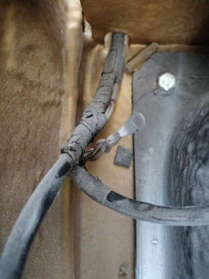
Found the female spade ground connector. Now to find it's home..
 

Attachments

  • 17848204811256249811245207623310.jpg
    17848204811256249811245207623310.jpg
    397 KB · Views: 17
the taillights or the engine?

help us help you!
I do indeed need a FI diagram. The wiring near the starter is boogered-up, and from previous replies, there are 2 white wires that I'll need to recreate and run to the proper terminals, since they were spliced together under the intake.
 
Found the female spade ground right where you said it was, near the tank.
screw it into the vertical metal between the tank + spare tire. there should be a hole there right above where the cables came through. the wiring that goes away from the back end of the car goes along the vertical panel to feed the sender at the fuel tank - pull it closer to the gap between the vertical piece and the gas tank
 
Sounds like a simple problem.

My earlier comment… Just saying.. if unplugging the taillight solves and/or creates the problem I thought it would might be simple to trace back from there …but… I see you have many extra slices and splices.


I have E12 blue book wiring diagrams and early E24 ETM if those help- I can scan and post …if you get to that point.
Good luck.
 

Attachments

  • IMG_9632.jpeg
    IMG_9632.jpeg
    461.3 KB · Views: 5
I do indeed need a FI diagram. The wiring near the starter is boogered-up, and from previous replies, there are 2 white wires that I'll need to recreate and run to the proper terminals, since they were spliced together under the intake.
They supposed to be spliced together

Did you get a copy of the schematics yet?
 
Back
Top