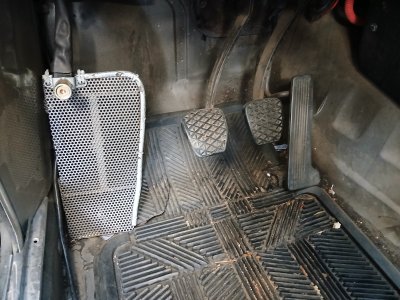
Dead Pedal DIY

That would be the bend for the bottom, top part is bent down at 90 degrees which was what the V-notch was creating. I hadn’t noticed that when looking at your initial drawing. So same idea just squared off so that joint line is one flange width down the top riser portion. Fusion is quite cool…
Yes, left as an exercise for the reader... :cool:
 
Given the short top section of the actual pedal, you can probably just leave the added tag on the lower section long, and it will go all the way to the end of the top section. No need to have that third bend.

If it is steel, then I'd run a weld bead along that open edge, and grind it over so it matches the bent edge. Once it is powder coated you wont be able to tell the difference.

Screenshot 2026-10-29 at 8.22.23 AM.png


Screenshot 2026-10-29 at 8.21.30 AM.png


I found that if you bend at the center line, you will need to cut back the edges that join by about 1/2 the bend radius. I also reduced the relief cutout to Thickness*3, smallest it would accept.

Also went to a 1mm bend radius.
 
Last edited:
While doing a general search, I came across a CSL with the Alpina dead pedal. Here are two pics. It looks like an easy install process.

E9 with dead pedal.jpg

E9 dead pedal side view.jpg
 
I still think I may make one with vertical ribs like the accelerator pedal. Maybe from billet aluminum, or possibly just 3D print it. Classier, IMO...
 
At 6’5” I want all the legroom I can get and after just returning from a 1,000 mile five day drive in the Sierra with two other e9 coupes and an e24 B10 Alpina, I would be cramped with a dead pedal.
IMG_3847.jpeg
IMG_3861.jpeg
IMG_3838.jpeg
IMG_3837.jpeg
 
Ya know, it's really impressive how many have taken an iterest in my dead pedal (aka foot rest) post project. It's even more impressive to see so many detailed and technical drawings. When I first came across one photo of an E9 dead pedal (on a CSL race car, I think), I noticed the complex design and angle of the top portion. I only made a quick assessment of the mounting area and presumed it was going to be tricky. Being a DIY kinda guy, I already purchased materials to make one out of wood and aluminum diamond plate.

Yesterday, I finished all I could on my CSi (waiting again for parts) and had time to begin the dead pedal project. I took a closer look at the mounting area and where the base of the dead pedal would mount. The dimensions I picked are 11"x3.5". I cut a block of wood to that size and fitted it where it should mount. I could easily mount a piece of wood that size right there using nothing more than two 1.5" metal 90-degree brackets. There is a gap one-third of the way from the top of the mock-up dead pedal about 5" long due to the curvature of the floor and footwell sheetmetal. Being a perfectionist, I wanted to fill in that gap so the dead pedal was firmly supported, even though a 1.5" thick block of wood that size would hardly flex at all.

I used a tool I almost forgot I even had... a contour gauge. I don't intend to cut away the factory carpeting and want to keep it intact. My perfectionist tendencies do have limits. I then made a cardboard template to test my measurement. It was a perfect fit. Now, all I had to do was figure out what to use to create that curved 3D structure to attach to the base of my dead pedal. Wood! I only have simple tools and more than a few power hand tools. I used my miter saw and bench grinder to eat away as much of the wood as possible so the sanding part would be minimal. So far, so good!
IMG_6365.jpeg
IMG_6366.jpeg
IMG_6367.jpeg
 
the question i have for you is, do you have the foam in place between the firewall / filler panel and the carpet? the foam creates somewhat of a dead pedal ...
 
the question i have for you is, do you have the foam in place between the firewall / filler panel and the carpet? the foam creates somewhat of a dead pedal ...
I've heard of that foam piece and do not have any such thing. I basically made one out of wood. It's a simple curved shape, not complex as I first thought.
 
Looks good! One thing - looking at the background of your photo, do you have the quick jack correct side forward? My recollection was that the sticker was on the "heavier" i.e. front side of the mechanism. But I may be mis-remembering on what side the sticker sits and am not at home right now to check.
 
What we made. Not as pretty as the Alipina unit, but highly functional.

Dead Pedal more aligned with accelerator pedal than clutch/brake.

Wide enough various types of footware and in a very comfy spot.

Still playing with location Aux Lights toggle foot switch. Like Dad's old stationwagon ;)
It switches between the 7in and 5in driving lights.

Hth
 

Attachments

  • 20261101_132041.jpg
    20261101_132041.jpg
    351.6 KB · Views: 23
Looks good! One thing - looking at the background of your photo, do you have the quick jack correct side forward? My recollection was that the sticker was on the "heavier" i.e. front side of the mechanism. But I may be mis-remembering on what side the sticker sits and am not at home right now to check.
Yes... Quickjack is right. Otherwise, it would not lift the car properly. The piston side goes forward with the pistons facing outward as there is a definite left and ride side.
 
What we made. Not as pretty as the Alipina unit, but highly functional.

Dead Pedal more aligned with accelerator pedal than clutch/brake.

Wide enough various types of footware and in a very comfy spot.

Still playing with location Aux Lights toggle foot switch. Like Dad's old stationwagon ;)
It switches between the 7in and 5in driving lights.

Hth
A "form follows function" solution. Mine will be a bit more refined, but crude compared to what others would do. For example, I will cover the wood block in aluminum diamond plate, but cut and screwed on vs. bent. I don't have a machine shop at my disposal. I felt 3.5" in width was ideal as to provide a good platform while staying far enough away from the clutch pedal. I will post a pic of the finished product, which will be in the coming days.
 
OK, here's the mockup in Fusion. Note that seams are not directly adjoining because Fusion won't allow that, the idea is that that gap is welded closed. Does this look like the original or close enough to make it worth printing one out? Before printing in metal I'll probably print in plastic - cheap and I can do it at home. Regarding the face, can decide on that, open to options.

Screenshot 2026-11-02 at 2.23.06 PM.png
Screenshot 2026-11-02 at 2.22.35 PM.png
Screenshot 2026-11-02 at 2.21.24 PM.png
 
OK, here's the mockup in Fusion. Note that seams are not directly adjoining because Fusion won't allow that, the idea is that that gap is welded closed. Does this look like the original or close enough to make it worth printing one out? Before printing in metal I'll probably print in plastic - cheap and I can do it at home. Regarding the face, can decide on that, open to options.

View attachment 229183View attachment 229184View attachment 229185
Terrific drawings! The thing is, the angled part at the top of the structure isn't needed unless you mount it closer to the clutch pedal. There is plenty of flat space to mount it closer the left that places the dead pedal in a nice comfortable position. Not sure why many think it needs to be so far to the right.
 
OK, here's the mockup in Fusion. Note that seams are not directly adjoining because Fusion won't allow that, the idea is that that gap is welded closed. Does this look like the original or close enough to make it worth printing one out? Before printing in metal I'll probably print in plastic - cheap and I can do it at home. Regarding the face, can decide on that, open to options.

View attachment 229183View attachment 229184View attachment 229185
yes, it looks quite close.
 
Made a little more progress on my dead pedal project. Today, I hope to cut the diamond plate that will encase the wood block base I made. Besides doing the job, I think many will be surprised at the cosmetic idea I have once finished. As the Zen Master says, "We'll see."
IMG_6377.jpeg
IMG_6380.jpeg
IMG_6379.jpeg
IMG_6381.jpeg
 
Over the past three days I cut the diamond plate to size, primed the pieces, painted the pieces, sanded the foot rest plate, and then gave it a wrinkle-finish clear coat. It turned out almost as I intended-- not a polished looking part that you would buy, but nice enough to mount and use. I still have to mount it.
IMG_6398.jpeg
IMG_6404.jpeg
IMG_6405.jpeg
IMG_6403.jpeg
IMG_6402.jpeg
 
Looks great! And love that it’s homemade; that’s the spirit. If one is critiquing, and I say this with the understanding that I have ended up in the same place, there’s this weird balance between the American hot rod racing stuff that one finds on summit racing or equivalent and the sometimes (slightly) snobby but refined quality of the German style and engineering. Totally respect your handiwork and creativity in making this, and clearly your simple question two weeks ago spawned an entire discussion and on my end a few hours of fusion mockup and printing which has not yet reached its conclusion, and yet it’s funny how the simple detail of crosshatching on the steel plate says American not German.
Love how you’ve thrown yourself into your e9 with both feet though! Long love affair ahead. Lots of heartache and headache (x2) but much reward. Plan to bring it to Monterey next year…
And I keep coming back to edit this because I realize it sounds negative which is not the intent. More just to say it’s hard to live up to what the car seems to demand…it’s like an uncompromising partner - close enough sometimes is a mile away, in the most obnoxious way possible
 
Last edited:
Back
Top