I know we don't hear from coupeking often but they make the Getrage 265 transmission reinforcement, maybe they can make this too?these have been on backorder for over a year. somebody else needs to start making these. paging @halboyles or @alprada70
You are using an out of date browser. It may not display this or other websites correctly.
You should upgrade or use an alternative browser.
You should upgrade or use an alternative browser.
1972 3.0CSi - Riviera Blau Puzzle Project
- Thread starter Cyrano
- Start date
-
- Tags
- uitlijning
Hi there,
The last few days were pretty active, even if I cannot spend as much time as I would like on the car.
The front and rear main supports were removed from the car. That allowed me to check a few things:
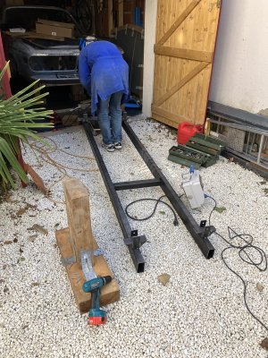
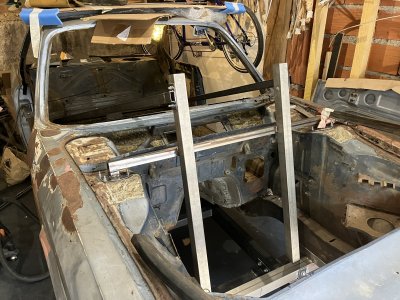
I am currently building a subframe to maintain the car in position during the body restauration.
I first replaced the axle supports with homemade ones. This was done pretty quickly. Bello is the rear support during final fitting before welding.
The next step will be to install 2 main axial beam under the front and rear supports to make a complete frame.
In order to make the frame easier to manage (beams are heavy!), I plan to bolt the beam to the support, not weld them. That will limit the difficulties during installation and removal of the car on the frame.
It is not done yet, and should be completed in the next few days.
The last few days were pretty active, even if I cannot spend as much time as I would like on the car.
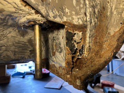
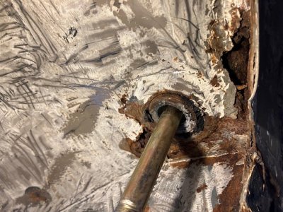
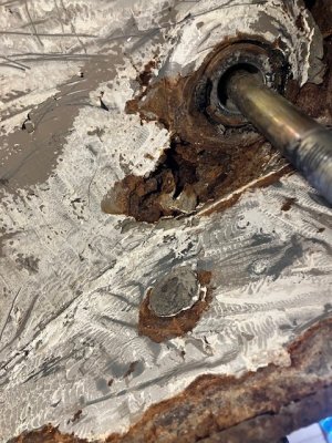
The front and rear main supports were removed from the car. That allowed me to check a few things:
- Front: I bought a spare front axle support with the whole car. I installed it to check if it fits after removing the original one. The spare front support could be installed with good alignment. This is a fairly good news.
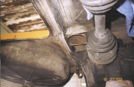
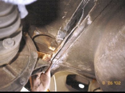
- Rear: The removal of the rear support allowed me to finish the cleaning of the protective coating. The bad news it that there are a lot of rust in the rear attachment screw, on the right side of the car. I will look at this in depth during the sill removal to see what must be changed.


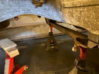
I am currently building a subframe to maintain the car in position during the body restauration.
I first replaced the axle supports with homemade ones. This was done pretty quickly. Bello is the rear support during final fitting before welding.

The next step will be to install 2 main axial beam under the front and rear supports to make a complete frame.
In order to make the frame easier to manage (beams are heavy!), I plan to bolt the beam to the support, not weld them. That will limit the difficulties during installation and removal of the car on the frame.
It is not done yet, and should be completed in the next few days.
Hi there!
Some news on the project. The sub-frame took us more time than what I thought. The issue was not only to build the frame but make sure that we could dismantle it without cutting it in pieces once all the bodywork is done. Anyway, it is moving forward.
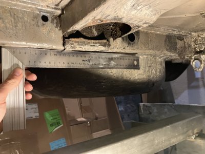
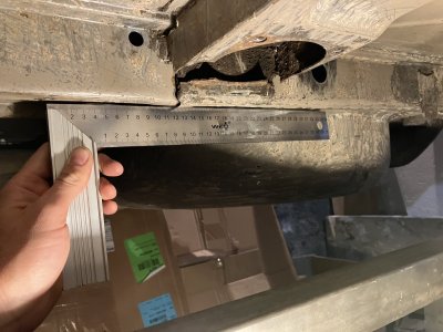
Before attaching the differential support, we took the opportunity to around it. The transverse support was slightly bent, and I put it back straight before to fit to the sub-frame. The material at the breach location was really soft and I wonder if it could have been annealed by the ageing/constraint (multiple bending/unbending). I will have to add a backplate to strengthen the overall assembly. A future fun task!
Differential Support, showing the bend.
Putting the support back straight, before final fitting of the bench frame:
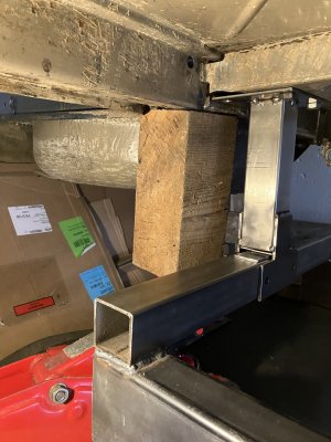
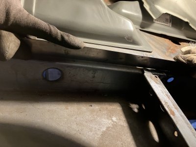
Bench Frame - not yet completed:
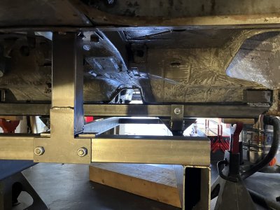
This is not a complete surprise, but I have now the assurance that the right side is shorter than the left side on the door area (distance between door hinge support on A-post and the door lock on B post is 5mm off). The weird thing is that I cannot find evidence of the bend in any other area around the fender, except a small bend on the front windshield frame.
I need to look into details on how to measure the fixation points of the front and rear supports to verify if the “A-post – B-post” distance issue is linked to the repaired rail frame. I don’t have the feeling this is the case but would prefer to measure it if I can.
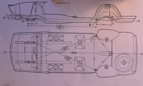
Some news on the project. The sub-frame took us more time than what I thought. The issue was not only to build the frame but make sure that we could dismantle it without cutting it in pieces once all the bodywork is done. Anyway, it is moving forward.
Before attaching the differential support, we took the opportunity to around it. The transverse support was slightly bent, and I put it back straight before to fit to the sub-frame. The material at the breach location was really soft and I wonder if it could have been annealed by the ageing/constraint (multiple bending/unbending). I will have to add a backplate to strengthen the overall assembly. A future fun task!
Differential Support, showing the bend.


Putting the support back straight, before final fitting of the bench frame:


Bench Frame - not yet completed:

This is not a complete surprise, but I have now the assurance that the right side is shorter than the left side on the door area (distance between door hinge support on A-post and the door lock on B post is 5mm off). The weird thing is that I cannot find evidence of the bend in any other area around the fender, except a small bend on the front windshield frame.
I need to look into details on how to measure the fixation points of the front and rear supports to verify if the “A-post – B-post” distance issue is linked to the repaired rail frame. I don’t have the feeling this is the case but would prefer to measure it if I can.

Attachments
Hi,
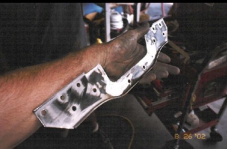
My CSi had the same crack at differential mount about 22 years ago. Some guy that I can’t remember his name in Los Angeles adopted this support
My CSi had the same crack at differential mount about 22 years ago. Some guy that I can’t remember his name in Los Angeles adopted this support
Attachments
I sell the 2 piece new design supports. Same basic design but better

Hi guys,
Some news, great progress and a few surprises.
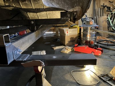
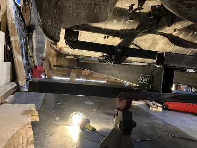
The frame has been completed. I will install the wheels a bit later on the lower support. I do not need to move the car immediately anyway, so I have some time to think about the best option.
I am pretty happy with the result as the whole assembly is quite stiff. Not sure if I need to fit anything else to make the assembly even more robust. If anyone has a suggestion, please feel free to share!
We made measurements of the body dimensions. We measured twice the dimensions (2 days apart) and found the same value at +1mm, using a scribe and a laser pointer. We found a difference of 5mm between the left side (+2mm long compared to nominal) and the right side (-3mm short compared to nominal). We also identified a slight tilt between the front and the rear axis (~3°).
I am not sure if I should be concerned with these numbers. I would say "no" given the age of the lady but a few experts here may have other thoughts.
Inspecting the body details here and there, I noticed a few areas where the metal sheets are still slightly bent, remainders of the bent and repaired right front rail. I don’t think there was anything critical.
I plan to remove the front fender to look a bit further in the A post area. I need to see how I can bring it forward to put it back where it should be, and evaluate options.
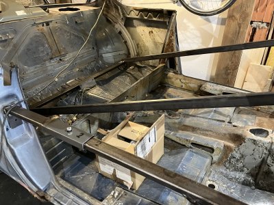
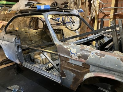
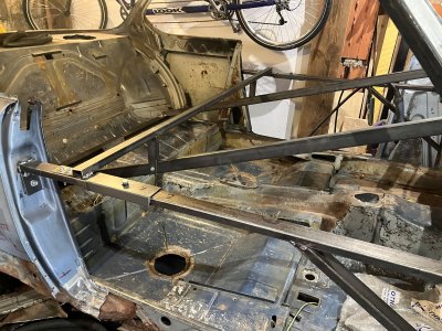
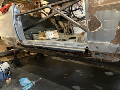


That's a serious frame you are making.
The rust at the 2 large screws at the rear axle is a though spot, as the floor is double there; on the inside you can see the thicker plate spotwelded on top. Water creeps in from below, eating away from the inside.
Additionally, often the rust also eats the sill in that vicinity, making it a complex piece to recreate.
tdgray
Well-Known Member
Very sturdy indeed… that’ll work.
Hello everyone,
A few recent developments.
I have spent the last few weeks taking measurements under the car to get a better feeling of the situation. It is not the only thing I have done… but this is the one that is concerning me the most at the moment as I am not able to get a clear view.
We went back and forth on this activity with my father, and here are the main trends after several sets of measurements:
2 last things:
The more I dig into this and the more gaps and issues I find… Maybe I’m gonna stop now the investigation and put back everything on the body as is… Just kidding!!! But still… I was not expecting such a big mess!!
Question to the members :
Have a nice day everyone!
A few recent developments.
I have spent the last few weeks taking measurements under the car to get a better feeling of the situation. It is not the only thing I have done… but this is the one that is concerning me the most at the moment as I am not able to get a clear view.
We went back and forth on this activity with my father, and here are the main trends after several sets of measurements:
- Gap between diagonals (Rear Right to Front Left vs Rear Left to Front Right, red arrows) : about 7mm.
- Gaps between the straight lines (Rear Right to Front Right vs Rear Left to Front Left, green arrows) : about 2mm.
- It seems that the front axle is not centered over the car longitudinal axis. The gap is about +5mm left and -5mm right, but I cannot locate exactly the centerline (blue arrows). I mean that locating the exact centerline and making sure it is not slightly offset is a pretty difficult exercise.
2 last things:
- There is a slight offset of 4mm at the top of the right A pillar (going backward), which generated a slight over height of the roof (about +3mm greater compared to the left side).
- The valence is showing a significant tilt compared to the frame rail alignment.
The more I dig into this and the more gaps and issues I find… Maybe I’m gonna stop now the investigation and put back everything on the body as is… Just kidding!!! But still… I was not expecting such a big mess!!
Question to the members :
- Are the gaps identified in 1, 2 and 3 significant concerns for the car stability and behavior. I assume they are but on these old ladies, we never know.
- If confirmed, what would be the best option to put everything back straight? I mean, shall a full replacement of the frame rail be required, or unbending is a viable option? I contacted a few workshop around and I am waiting for a few responses. But I assume that experts here may have very valuable inputs.
Have a nice day everyone!
Incredible work you are doing to save this coupe, the difference in your measurement has to be from one of the front rails being bent… If you’re really concerned, I would establish a centerline on the car with a string and work from that out to bolt holes/mounting points to confirm/find the difference.
I think you should ask Paul Cain for help.
He is the man for this job and he likes France!
He is the man for this job and he likes France!
I would suggest to check how the front and rear are off the center as if your measurements are precise there is a shift there.
According to #2 you are still within the tolerance from the drawing +/- 2[mm] but as you would be removing all the seals it can be improved probably.
The condition of the body (rusty etc) is not stiff enough for the can to keep straight.
The shift (assuming how E9 body is "flexible") could come from the situation where front or rear wheel hit or got hit from other car or object (eg. winter slippery roads).
Laser-based check should disclose the point where the bent is located (complete frame, half or region). Construction laser are widely available with enough power to generate lines along the whole chassis.
Hmm, interesting but challenning situation.
I do not have a direct answer, but I get a feeling your car isn't straight, or at least not within tolerances.
A few questions to deep dive:
1. Can you give us the values of the dimensions of 1); the red diagonals?
2. How do you conclude that the front axle is off centre by ~5mm? Can you share pics/measurements?
2. When looking from the underside, the frame rails are supposed to be perfectly parallel. The following requires you to find the car's center, but I would spend the time for that effort: are the two frame rails parallel to the car's center?
I think the ~7mm deviation is soo large vs +-2mm tolerances (so 4mm difference between both min and max tolerance values), that you have a hard time getting a ice, parallel hood to fender fitment.
I can measure the underside of my car if that offers any help.
Maybe look closely at a center bearing? There is a built in offset to measuring points in the chassis.
Be cautious picking your reference points.
I have a car on the frame rack now if you need some measurements.

Be cautious picking your reference points.
I have a car on the frame rack now if you need some measurements.
Guys,
Thanks a lot for the feedback, guidance, and thoughts.
I’ll try to provide more information on the approach I used for the measurements. I took a few pictures so you can figure out what I am talking about. Sorry in advance for the messy garage.
Step 1:
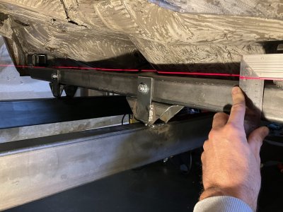
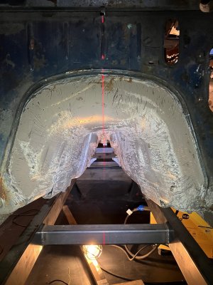
Before taking any measurements, I ensured there was no tilt (rear/front and left/right). I used my construction laser for that. Below are the pictures.
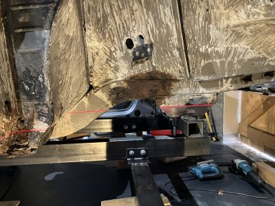
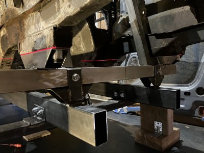
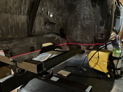
Note 1: You can see on the central picture that the laser line hit both left and right frame rail supports at the same .
Note 2: I found a slight tilt between the front and the rear. When front frame rails are aligned, the gap between the left and right rear post is about 9mm. This equates to an angle of 0.5 degree, which is negligible (10mm over 1236mm).
Step 2:
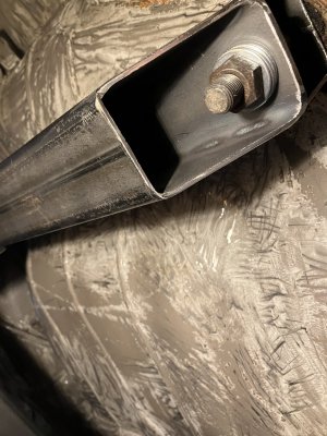
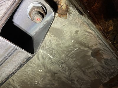
To ensure that I was pointing on the same spot for all the measurements, I made a cross on the screw head or the screw. Taking into consideration the I assume that there would be a 1mm error, due to the pointer diameter and naked eyes alignment. This is also one of the reason why I took the same measurement in different days... to make sure I make the same mistake consistently!
Step 3:
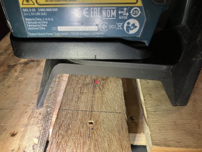
All the measurements were made using a long flat piece of wood (exotic to reduce impact of humidity) by pointing the upward laser point to the screw or screw head and reporting the downward point to the piece of wood. I then used a ruler to read the measurement. Again, there is also in this step a potential for error, but I assumed it to be the same for all the measurements taken (left and right).

Here after are the measurements for each dimension:
* Reported values are raw measurement, not corrected to the expected projection from the drawing.
Concerning the centerline identification, I proceeded per the below:
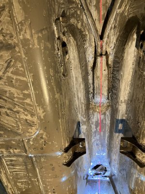
Line crosses perfectly the hand brake box and the center hole of the gear box lever entry.
I then measured the dimensions using the drawn center points:
In a nutshell, the centerline is not at the center… There is probably some magic here…
Below is the drawing with the reported dimensions:

Thanks a lot for the feedback, guidance, and thoughts.
I’ll try to provide more information on the approach I used for the measurements. I took a few pictures so you can figure out what I am talking about. Sorry in advance for the messy garage.
Step 1:
Before taking any measurements, I ensured there was no tilt (rear/front and left/right). I used my construction laser for that. Below are the pictures.


Note 1: You can see on the central picture that the laser line hit both left and right frame rail supports at the same .
Note 2: I found a slight tilt between the front and the rear. When front frame rails are aligned, the gap between the left and right rear post is about 9mm. This equates to an angle of 0.5 degree, which is negligible (10mm over 1236mm).

Step 2:
To ensure that I was pointing on the same spot for all the measurements, I made a cross on the screw head or the screw. Taking into consideration the I assume that there would be a 1mm error, due to the pointer diameter and naked eyes alignment. This is also one of the reason why I took the same measurement in different days... to make sure I make the same mistake consistently!


Step 3:
All the measurements were made using a long flat piece of wood (exotic to reduce impact of humidity) by pointing the upward laser point to the screw or screw head and reporting the downward point to the piece of wood. I then used a ruler to read the measurement. Again, there is also in this step a potential for error, but I assumed it to be the same for all the measurements taken (left and right).


Here after are the measurements for each dimension:
| Dimension | From Rear Right (mm) | From Rear Left (mm) | Limits (mm) | Gap to nominal (mm) |
| Y | 2401 | 2393,5 | 2398 ± 1 | +3mm ; -4,5mm |
| X | 2403* | 2404.5* | 2390,7 ± 2 | 1,5mm |
| V | 2587 | 2580 | 2584 ± 1 | +3mm ; -4mm |
* Reported values are raw measurement, not corrected to the expected projection from the drawing.
Concerning the centerline identification, I proceeded per the below:
- 1st: I used the laser from the entrance of the tunnel and pointed toward the back of the car. I used the hand brake box as the 2nd point to draw the line. This line seemed to be well aligned with the car body, so I used it to draw a point at the rear support location. I also took the opportunity to place 2 points on the tunnel.
- 2nd: I then placed the laser under the point marked on the rear support and then pointed toward the front (using the points in the tunnel). I used that line to draw a point on the front support.


Line crosses perfectly the hand brake box and the center hole of the gear box lever entry.
I then measured the dimensions using the drawn center points:
- At the rear of the car:
- From the right to the centerline, a gap of -6mm is measured (612mm vs 618mm expected).
- From the left to the centerline, a gap of +6mm is measured (624mm vs 618mm expected).
- At the front of the car:
- From the right to the centerline, a gap of -4mm is measured (measurement taken from the inside of the frame rail to the centerline).
- From the left to the centerline, a gap of +4mm is measured (measurement taken from the inside of the frame rail to the centerline).
In a nutshell, the centerline is not at the center… There is probably some magic here…
Below is the drawing with the reported dimensions:
Last edited:
Hmm, interesting but challenning situation.
I do not have a direct answer, but I get a feeling your car isn't straight, or at least not within tolerances.
A few questions to deep dive:
1. Can you give us the values of the dimensions of 1); the red diagonals?
2. How do you conclude that the front axle is off centre by ~5mm? Can you share pics/measurements?
2. When looking from the underside, the frame rails are supposed to be perfectly parallel. The following requires you to find the car's center, but I would spend the time for that effort: are the two frame rails parallel to the car's center?
I think the ~7mm deviation is soo large vs +-2mm tolerances (so 4mm difference between both min and max tolerance values), that you have a hard time getting a ice, parallel hood to fender fitment.
I can measure the underside of my car if that offers any help.
I already installed the hood and the situation was not so bad actually.
My main concern is more car stability and driving consistency. Not sure if the gap observed is critical, given that the car is know for being flexible. I won't make it a race car, but I don't want to have to turn left in order to drive straight.
When you say that the frame rails are perfectly parallel, do you mean that the inner wall of the frame rails are parallel? I am asking this because the thickness varies all along the length.
Or you mean that there shall be an equal distance from left and right of the centerline in each area?
Thanks!
The last bit is what I mean: ...there shall be an equal distance from left and right of the centerline in each area".
Maybe look closely at a center bearing? There is a built in offset to measuring points in the chassis.
Be cautious picking your reference points.
I have a car on the frame rack now if you need some measurements.
Hi sfdon!
Can just confirm that the centerline is indeed right in the middle of the car? I know that sounds a bit weird...
Based on the measurement I took, it is slightly offset on 1 side of the car. But maybe what I considered as the centerline per my post just above is not correct...
Thanks for the help!
Last edited:

