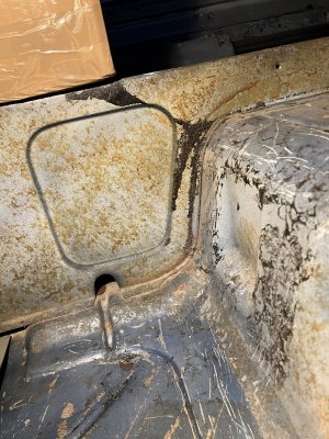
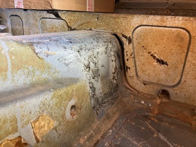
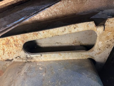
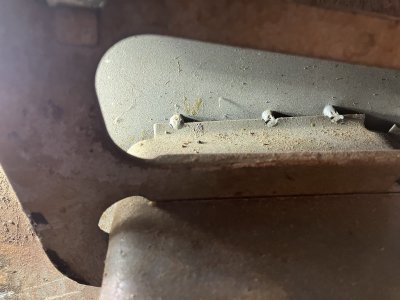
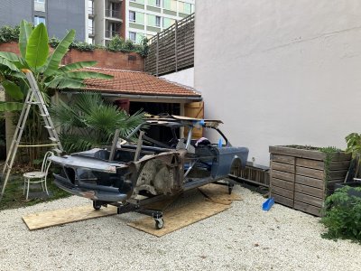
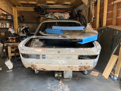
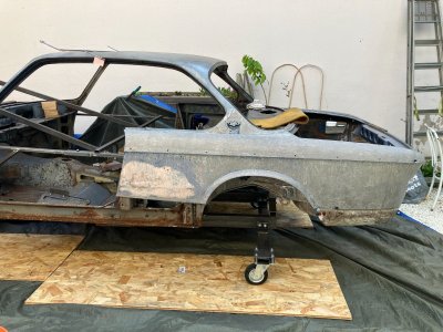
1972 3.0CSi - Riviera Blau Puzzle Project

Are the condition for the measurements done with the same conditions (what are the conditions on the BMW plot than would be good to ask).

I know from few sources E9 (as other cars w/o frame in 60's-70's) were flexible and thus sensitive to all the parts which are on the car. I heard stories about the cars which were perfectly aligned but have lost the alignment once the engine, suspension and glass/heavy parts were mounted.

Might it be it is somehow related to the way car should have been verified for proper dimensions but also some repair panels are not made from the steel type they have been in the factory (gauge, carbon content...).

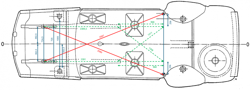
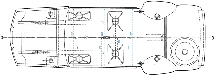
From some reason BMW has not provided front and rear part divided into two dimensions (as they are hard to be measured). What is more, looking on the distance from the differential mount to rear suspension mounts dimensions are different - there is no symmetry there by factory. I would rather than measure total distance as provided on the chart rather than dividing it by symmetry line.

Have you been also checking symmetry on the outer shell to check if they are following suspension/floor assymetry? Than could in some cases confirm body deformation as they are all connected by welds.

I would not be surprised that at least some of the asymmetry came from rust and sills weaker structure combined with chassis fatigue due to age/condition of the car (still assuming no "situations" on the roads in the past).

It is the question how many people are making that measurements during restoration. It would be expected they will step-in and share their experience.
 
Hi guys,

Thanks again for the contribution and sharing the experiences!

Now that I draw the centerline and noticed that there was an offset on the rear support and front support, I went in the inside of the car to look for any potential bend or suspect area.

Here is what I found:

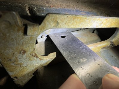
At the back of the car, the gap between the stiffener plate (that holds the back seat) and the tunnel is not existant on the right hand side, but is about 10mm on the left hand side. Based on a few pictures I could see on other members restoration projects, there should be a gap on both sides.

Picture of the right side of the stiffener plate and tunnel: No gap!
IMG_4573.JPG


Picture of the left side of the stiffener plate and tunnel: 10mm gap
IMG_4575.JPG


In the middle of the car, the right front seat support is flush with the tunnel. But the left front seat support is not flush and about +5mm away. We can see the welding quality is very different.

Right support and tunnel are perfectly flush on the right side:
IMG_4574.JPG


Left support and tunnel show a gap of +5mm on the left side (see the shape of the welding).
IMG_4576.JPGIMG_4577.JPG


Based on these additional investigation, I have the feeling that the tunnel was not centered (or already misshapen) while welded into place at the factory... back in 1972...

Would that make sense?
 
Yes, it make sense.

I join (later and in a other plant, not bmw) more than once the discussion, if an production fault is saleable or not.

If there is an gap under there carpet, cars would be sold as they are.

When they recognize it, they correct the fault and that's it.

My Mercedes has a repair at the roof skin definitely in the plant.

You won't believe how much body fault running out ro the customer...
All other means scraping it.
Nobody want that.

Breiti
 
I agree that what you find means that things in your car are non-symetric. But the tunnel "can't be" off-centre, as it's the first part laid down when the rest of the parts (sills, wheel arches, pillars etc) are being welded to it. The floor is 1 big pressing, the tunnel is not a seperate part.
For instance, the sills are just mated to the left and right edges of the floor, and thus the inner sill IS always equidistant from the tunnel's center. (unless the pressing of the floor is 5 mm larger on Left side and 5 mm smaller on right, which practically can't happen as it is a one piece steel pressing )You can confirm that by measuring, in the interior, from the side of the tunnel to the inside of the Sill. I think you will find that Left and right are within 1mm identical.

I'd rather think that the parts that are added to the floor+sills are off-center; for example the stiffener plate back seat: functionally only the top edge holds the rear seats, so when that is at the right height, it's function is fulfilled. The relative left right position isn't important, so seeing the 10 and 0mm gap to me wouldn't matter if I was the worker in the factory.
The seat supports also allow for some misalignment, as the the mounting points (the caged nuts) allow to slide the seats rails to their correct & parallel positions. After all, if the seat is 5 mm further to the center; who cares? As long as it freely slides front to back and the seat doesn't hit another vehicle component, it is functional.

I make this explanation as i think it means that although the pics you showed have non-symmetric elements, it doesn't mean (to me) that you've identified if (or why) your front or rear axle is mis aligned.

Biggest question to me (still) would be how the mounting points of the front and rear axle line up to the center of the car (=floor)
For this, i would mount 2 wooden sticks under the sills, running from left to right with the decorative trim panel unscrewed from the sill. One stick at the front, one stick at the back. Mark where the vertical plane of the inside sill falls onto the wooden stick. Then mark the middle of the wooden sticks.
From that, run a line (rope /laser) over it, to extend it to front and back so that you can verify the position of the axles and/or their respective mounting points.

Erik
 
Last edited:
I do agree with Erik and that leads me to the point in the past to check external body parts looking for non-symmetry there as sills and fender or pillars are critical and thus mounted to the floor panel at some points.
 
Hi there,


First, I thank you all for your very valuable response. I did not answer but took good note of your inputs.


I have not been able to respond quickly because I spend a lot of time taking measurements all over the car. This has been a very interesting (and tedious) process, but ultimately, I am now more confident in the situation and the way forward.


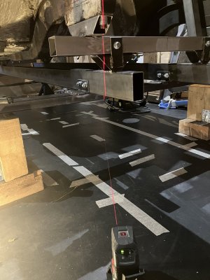
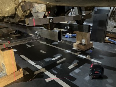
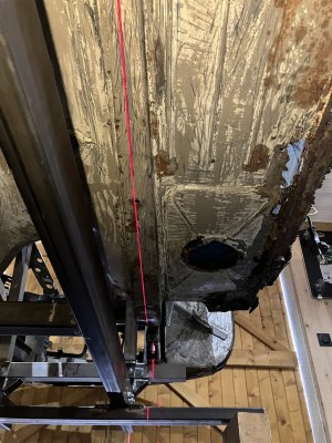
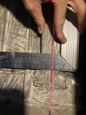
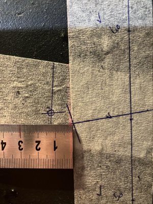
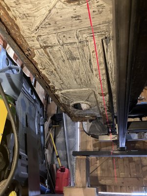
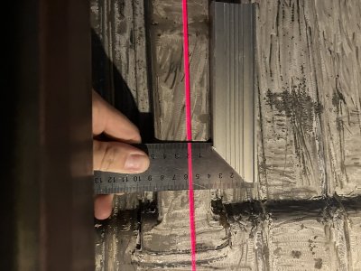
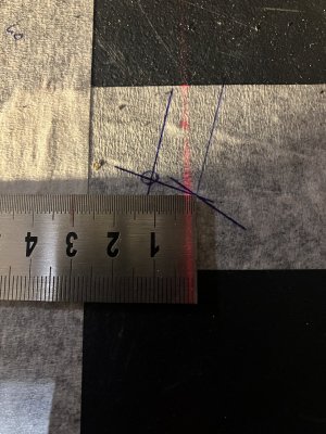
I initially used the laser pointer to point toward the measurement point. I finally abandoned this method to another one, which I feel more comfortable with. For each measurement point, I used the laser vertical line of the laser tool and marked a line on the floor (on masking tape). Using 2 lines allowed me to mark all the measurement points directly on the floor, draw lines in between, look for center lines and perpendicular lines, etc.


Assuming the floor is flat, the only caveat of this method is that you need to make sure which part of the car is leveled.
In my case, I started to make the measurements with the front support being fully aligned (front/back and left/right). With the front support aligned, I found that the whole body of the car was not leveled (e.g. door to door supports, front window frame, etc.). I finally aligned the back support area (left/right + front/back with the left front support) and took all the measurements again.


Here are a couple of pictures of the measurement approach, with the 2 laser lines pointing on the screw center point.

Measurement Method 1.JPGMeasurement Method 2.JPG


Below is a summary of the measurements

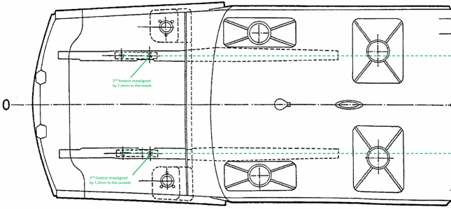
  • Overall measurements. The green doted lines have been drawn to verify how “square” the body was. Taking into consideration the measurement uncertainty, I believe the body is ok. However, the slight misalignment of the 2nd front support point is something I may have to look into.

Measurement Summary 1.png
Measurement Summary 3.png

Green doted line on the right:
Righ Rail Line.JPGRight Rail Mark.JPG2nd support R Alignment.JPG


Green doted line on the left:
Left Rail Line.JPGLeft Rail Mark.JPG2nd support L Alignment.JPG


  • Sill positioning compared to centerline (rear to front support). Difficult measurement as the sills are not perfectly straight. At least that gives an indication that the body is not completely offset.

Measurement Summary 2.png

Centerline:
Centerline alignment.JPG


Conclusion:
  • The whole body is in shape, except for the front right area. The front support is slightly off (1.5 to 2.0mm), but I am not sure that it is critical at that point.

  • The centerline based on the car body and the centerline based on the front and rear support centers are parallel but about 4mm off.

  • The right rail position is 5mm higher than the left rail. I’ll have to bring it back to its position.

  • The top of the right door post is off by 4mm. It may come back to position when I’ll work around the right rail. If not, I’ll help him a little bit! :cool:

Offset of the right front support when back supports and left support are leveled.
Right Front Support Height difference.JPG


Please let me know if you have any questions or if you would like to get more details on the measurements.


Next step will be to build the structure to unbend the front right rail! Another fun part!
 
Last edited:
Hi guys,


Long time no talk! Time flies and the project moves slowly. Balancing work, family time and restoration is not an easy task.


I spend the 2nd half of the summer trying to put the right front rail into position. But all attempts showed minimal improvement, not to say they were unsuccessful. Overall, while the sub-frame is good enough to support the car, it is not stiff enough to apply a reliable constraint on the rail and bend it.

I did not expect this, but in the meantime, this is good to see that while a significant constraint is applied on the car, it bends but always comes back to its position.


Anyway, to avoid getting to much into frustration, I decided to start working on the rear and the left side. The purpose was to reinforce the differential support (typical), reshape a few areas and start dismantling the left sill.


Here below is a quick summary of what was done:


  • Reinforcement plate of the differential support:
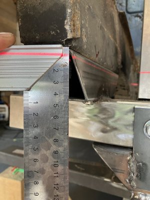
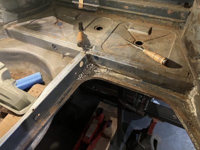
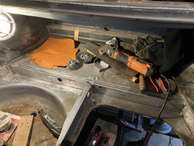
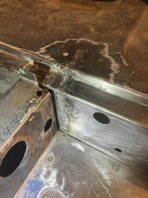
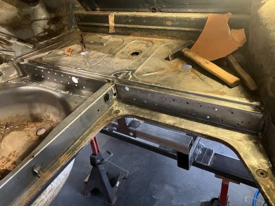
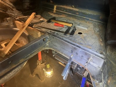
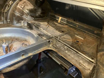
    • I started the reinforcement by welding reinforcement plate inside the trunk. The shape is a bit funky, but the purpose was to limit the potential bending of the reinforcement plate and ensure welding points are spread all over the existing support and are on the wheel wells too.
    • I then made the second reinforcement plate on the outside of the car. Welding points were made in such a way that the 3 metal sheets were welded together (inside + original + outside).
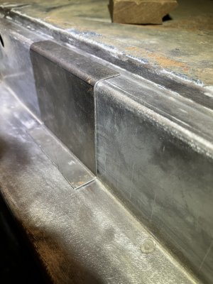
    • The differential support reinforcement plate will be designed, bent, and welded in a next step, as I would like the car to be on the side to ease the work.
Scratching the soft sealant and sanding the area
IMG_5155.JPGIMG_5162.JPG

Evaluating the bending pattern for the inner reinforcement plate:
IMG_5172.JPG

Welding the traverse crack and drilling holes for the spot welding.

IMG_5205.JPGIMG_5207.JPG


During and After welding:

IMG_5210.JPGIMG_5245.JPG

Outer reinforcement plate:

IMG_5247.JPG


If someone is interested in the support designs, I have them and can share the dimensions. Thanks everyone for the help in the thought process (with threads and PM).


  • Unbending of the spare wheel well. I’ll take care of the rusted parts once I’ll have a sand blaster. I'll share pictures once this area in completed.


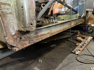
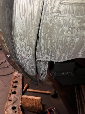
  • Cutting and unwelding of the left sill. I’ll keep only the inner sill as it is overall in good shape. Only the front inner sill is significantly rusted. I’ll replace specifically this part.

Car under rotation! :)

IMG_5284.JPG

Inner left seal and wheel well cut (only the welded area):
IMG_5414.JPGIMG_5417.JPG


Things are moving foreward. Not as quickly as I wish, but still encouraging progress.

The greatest progress is maybe the color trial made by my daughter on the rear fender! :cool:

IMG_5230.JPG
 
Hi guys,


Long time no talk! Time flies and the project moves slowly. Balancing work, family time and restoration is not an easy task.


I spend the 2nd half of the summer trying to put the right front rail into position. But all attempts showed minimal improvement, not to say they were unsuccessful. Overall, while the sub-frame is good enough to support the car, it is not stiff enough to apply a reliable constraint on the rail and bend it.

I did not expect this, but in the meantime, this is good to see that while a significant constraint is applied on the car, it bends but always comes back to its position.


Anyway, to avoid getting to much into frustration, I decided to start working on the rear and the left side. The purpose was to reinforce the differential support (typical), reshape a few areas and start dismantling the left sill.


Here below is a quick summary of what was done:


  • Reinforcement plate of the differential support:
    • I started the reinforcement by welding reinforcement plate inside the trunk. The shape is a bit funky, but the purpose was to limit the potential bending of the reinforcement plate and ensure welding points are spread all over the existing support and are on the wheel wells too.
    • I then made the second reinforcement plate on the outside of the car. Welding points were made in such a way that the 3 metal sheets were welded together (inside + original + outside).
    • The differential support reinforcement plate will be designed, bent, and welded in a next step, as I would like the car to be on the side to ease the work.
Scratching the soft sealant and sanding the area
View attachment 193175View attachment 193176

Evaluating the bending pattern for the inner reinforcement plate:
View attachment 193177

Welding the traverse crack and drilling holes for the spot welding.

View attachment 193180View attachment 193181


During and After welding:

View attachment 193182View attachment 193184

Outer reinforcement plate:

View attachment 193188


If someone is interested in the support designs, I have them and can share the dimensions. Thanks everyone for the help in the thought process (with threads and PM).


  • Unbending of the spare wheel well. I’ll take care of the rusted parts once I’ll have a sand blaster. I'll share pictures once this area in completed.


  • Cutting and unwelding of the left sill. I’ll keep only the inner sill as it is overall in good shape. Only the front inner sill is significantly rusted. I’ll replace specifically this part.

Car under rotation! :)

View attachment 193185

Inner left seal and wheel well cut (only the welded area):
View attachment 193186View attachment 193187


Things are moving foreward. Not as quickly as I wish, but still encouraging progress.

The greatest progress is maybe the color trial made by my daughter on the rear fender! :cool:

View attachment 193183
Thanks for sharing your experience. Liked it to read.
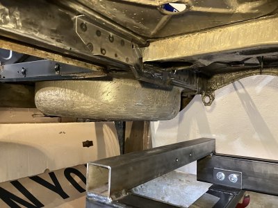
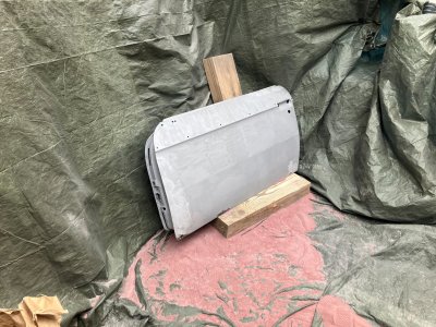
Little by little, and try to get the right energy off the restoration.
 
Back
Top