'72 Restomod

Layne

Well-Known Member
Site Donor
Messages
292
Reaction score
74
Hello friends, here I will chronicle my portion of the restoration and modification of this E9. I've been employed by the owner to finish the work on this car, it's not mine sadly, although it's giving me an itch to find one. Hopefully some of my ideas and experiences will be of use to someone. I'm working on it about 40 hours a week so hopefully this thread will be fast paced and interesting.
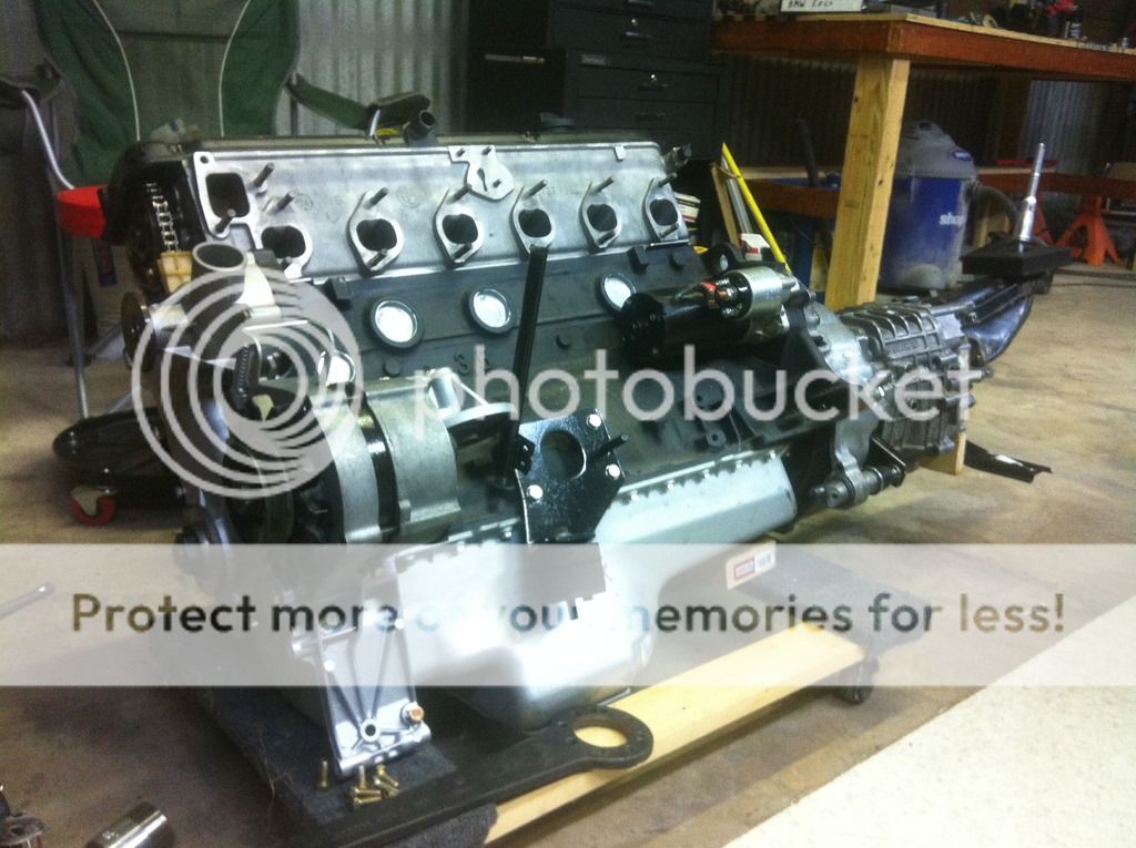
The car came to me already painted (space grey metallic, a newer BMW color), and with a rebuilt M30B34 engine that would turn out to have some problems. Suspension was rebuilt, but no brakes are installed. Everything else is pretty much in boxes.
IMG_1679[1].JPG

IMG_1683[1].JPG


I started off by removing the engine, as it had no fuel injection system or the transmission attached to it. While waiting for some engine parts I set about connecting the new small brake booster to the pedal. I found the booster bracket had been shortened to the point the clutch master cylinder could not fit and did not align properly with the pedal. So I made a new front end for the bracket and welded a portion of the old booster extension rod to the new booster to reach the pedal. I ended up doing a lot of re-bending on the brake pipes to make them nice and neat.
As it was:
3ad2fd5c6b43a578b2e19341c5cff240.jpg

Had to put the enigne back in for a minute to make sure my proposed booster location wouldn't hit anything...
2243a3dad933c0c5afaa780b0a619410.jpg


Remodified:
1fd047c6052f835f40d65a645f5076c3.jpg
99aada67b01ad4f77123329f5eb4a618.jpg
3381d55f8a3e17dce6365c4ded197e96.jpg

And all done:
90d506188620274673b4ca70562c99f8.jpg

At the same time, I found a fuel pump that would be suitable for the conversion to EFI. This is a kit from Tanks Inc. The only thing I could find that included a trough at the bottom to prevent fuel starvation. With any other option I would have had to add one somehow, probably by cutting a hole in the bottom of the tank and welding a trough in. This seemed like a good option and fits the shape of the tank well.
IMG_1775[1].JPG

59a512a8a0ddbb898afc860ed86050ba.jpg
1943fbc0965fe747aa396ab93bda8d24.jpg

Most of the clutch mechanism was missing so I had to buy new parts for that. All of the old-style clutch stuff is crazy expensive but all still available which is good.
0efc769e28444ac77bb954b7c5530a50.jpg
0b310a843db089006d07510d7fbb8a0d.jpg
 
Last edited:
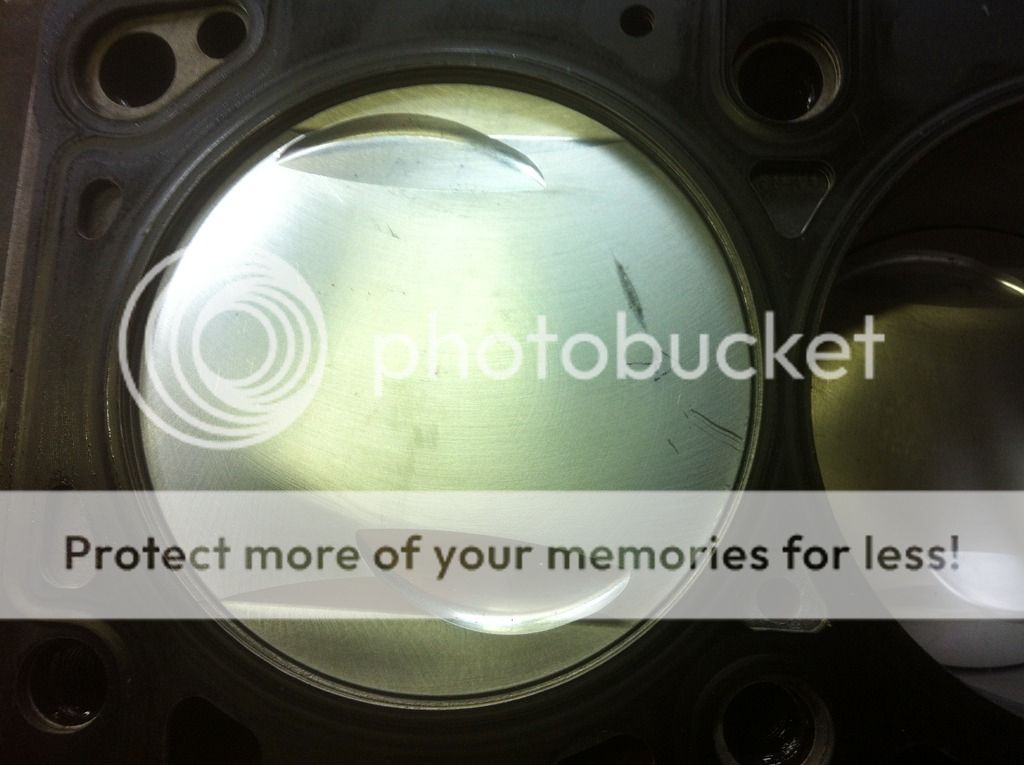
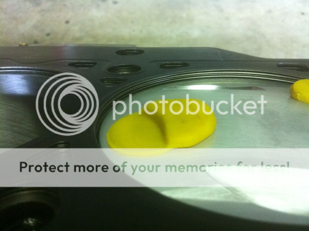
Along about this point, I attempted to rotate the engine and found it could only go about 1/3rd of a turn. To make a long story short, it would turn out that the timing chain tensioner had not been primed with oil, which makes it very easy for the chain to skip teeth, which it did. Easily fixed, and I added some Ireland Engineering upgraded rocker arms in the process. Buuuut when the head went back on, it still would not turn past TDC with the amount of force I was willing to apply. I found the pistons were striking the head and had been all along. Only barely interfering I suppose, as all 6 had a mark from hitting the head.


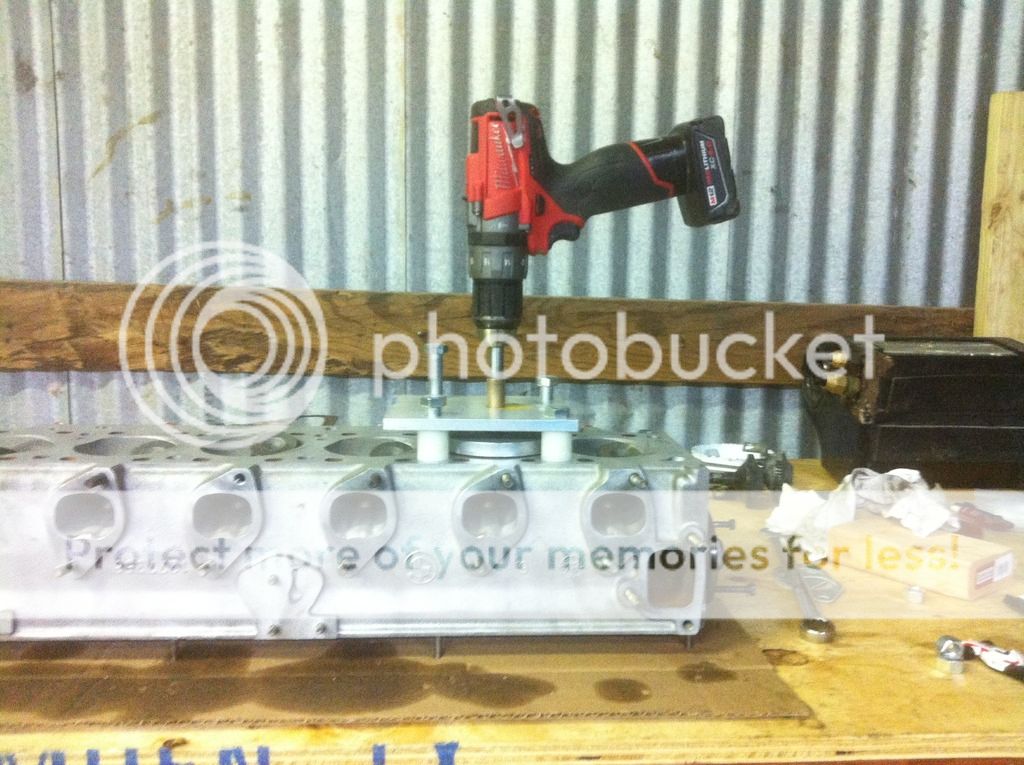
The engine builder must have rotated the engine all the way past all of the collisions (it hasn't been run yet). The pistons have a dome all the way across. I'm not sure what they're made for, they don't look directly suitable for any of the M30 heads I've seen. The best course of action (besides using the correct pistons in the first place) would probably be to pull the pistons and machine them to match the head, but I decided to take some material off the head as it was only interfering a little. This was a bit of a can of worms, as it was easy to make it no longer interfere, but it wasn't easy to get the 1mm or so minimum clearance that you should have between a head and piston. So I devised a jig that would make it easy to match the head shape to the piston shape while keeping each cylinder the same. Sort of like a large valve seat grinder, but it's just self adhesive sandpaper on a disc aluminum.


You can't really see it, but the disc has an angle all around the edge where the paper attaches. Maybe 5 degrees? I just eyeballed it to match the piston dome as closely as possible.


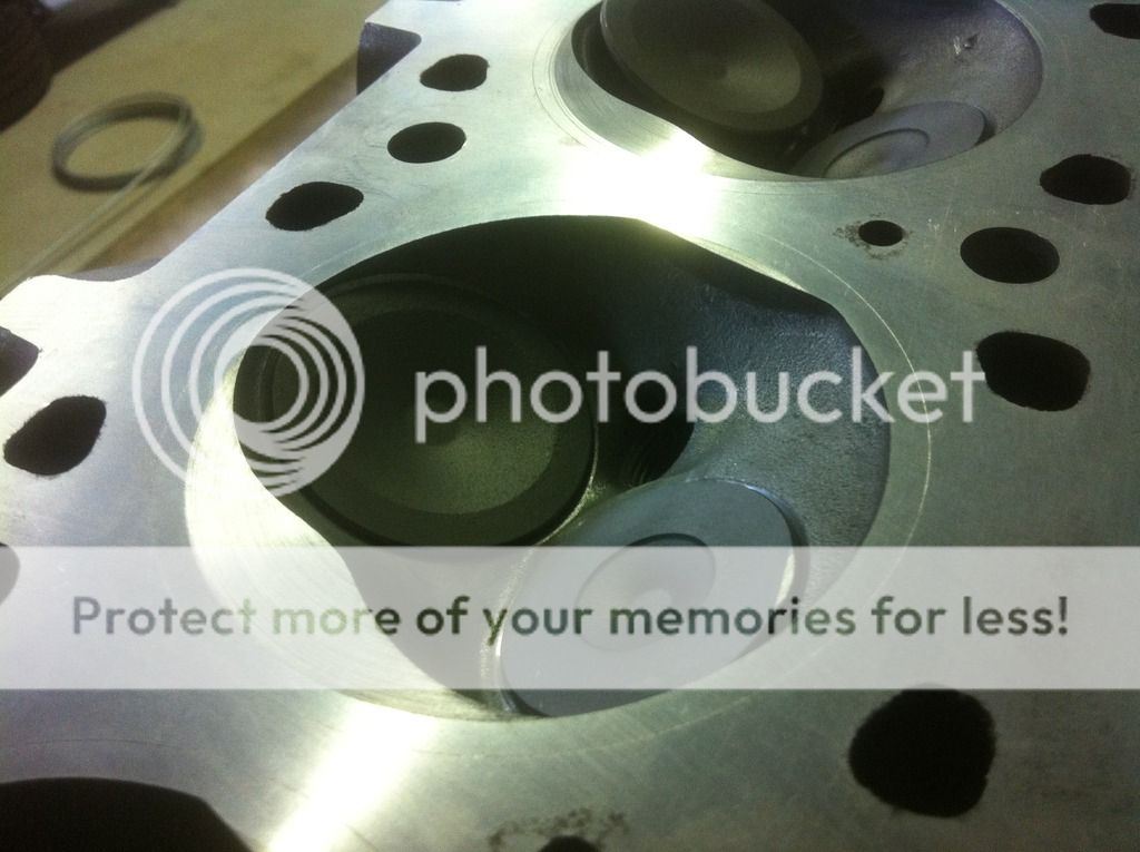
The results were great, it took very little time and effort to sand the head to where I needed it to be. I roughed it with 120 grit and finished with 320 and that was it.
After the rough pass:


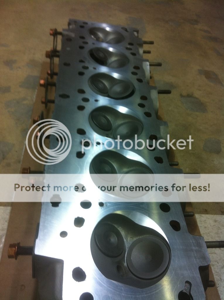
All finished:


Clearance is right at 1mm


Torqued the head back down and that's where I ended for the weekend. I finally have the EFI components on hand (motronic 1.3 from an M30B35), so I can start putting that together.
 
Last edited:
Nice work. Are you sure the head hasn't been cut below the minimum spec as I don't see any of the telltale marks/indentations which are used as a guide.
 
Nice work. Are you sure the head hasn't been cut below the minimum spec as I don't see any of the telltale marks/indentations which are used as a guide.

It measures .010" less than factory thickness spec. I only remember seeing one divot, near cylinder 2 in the above photo.
 
Not much worth photographing this week. I'm putting new connectors onto a B35 harness because someone can't tell sellable used parts from garbage. (every single time I buy used parts...)

Got the E12 shifter link and it's a perfect fit for converting the 4 speed to the newer style parts. Still a lot of slop from the pin hole in the transmission, so I ordered a reamer and oversized pins to tighten it up again.


Got all my AC components today! The pipes came from Yogi's, and everything else is Nostalgic AC Parts. Compressor is a Chinese Sanden 709 copy. I found that an ignition coil bracket is a perfect fit for the receiver/dryer (nostalgic doesn't sell brackets, weirdly). Going to mount that behind the right headlight, so less junk in the engine bay.


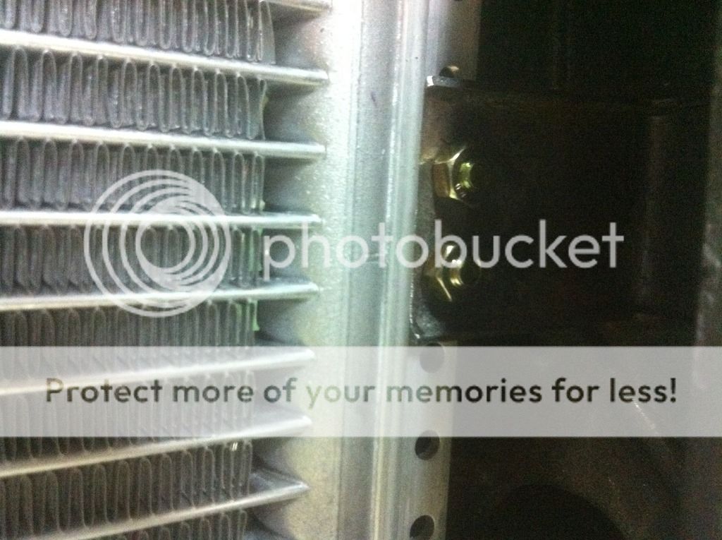
I took a chance and ordered the 16x22 condenser. I've seen others use a 16x18, but it's very very important to have the most condenser you can get. It's a perfect fit, provided you space it out in front of the radiator about 1.75". The radiator "hole" is not quite as big as the space up inside the nose. I'll probably have to make a skirt to fill in that 1.75" space so that air from my pusher fan doesn't escape out the sides instead of going through the radiator.
There's already some brackets there from the previous condenser or fan that will only take slight modification to mount the new condenser. There's already a hole on the top right side that the top line can go through (I think the wiring harness is supposed to go there, but it's going to have to find another route). And the bottom hangs down low enough that the bottom line is not impeded from entering the space behind the right headlight. So I don't have to cut anything at all.
 
It measures .010" less than factory thickness spec. I only remember seeing one divot, near cylinder 2 in the above photo.

Then be sure you get an adjustable cam sprocket. The A/C setup looks nice, you shouldn't need to place any baffles around the condenser. Are you replacing steel lines through firewall and if so are you using flare to o-ring adapters?
 
Then be sure you get an adjustable cam sprocket. The A/C setup looks nice, you shouldn't need to place any baffles around the condenser. Are you replacing steel lines through firewall and if so are you using flare to o-ring adapters?

These lines were copper, not steel, but yes I'm replacing everything right up to the evaporator and got flare adapters to go in that location. I considered going back with flared copper, as it's vastly easier to fabricate, but I figure they changed for a reason, prone to leaking most likely. Interestingly though, I just installed a mini-split AC in my shop and they use flared connections (same sizes as the car even). They supply a flare sealant with them, I suppose they're prone to leaking too.
 
You're doing some fantastic work there. You should be proud - getting familiar for when you find your own E9 project :)
 
Wait, I'm not convincedealing the valves won't spin even with the collet always in keeping pressure on the valve shafts. Too many other moving parts in the valve train to keep it from spinning.

Wouldn't it have been better to modify the pistons instead?
 
Wait, I'm not convincedealing the valves won't spin even with the collet always in keeping pressure on the valve shafts. Too many other moving parts in the valve train to keep it from spinning.

Wouldn't it have been better to modify the pistons instead?

You're misunderstanding something... It won't make any difference if the valves rotate, but they generally do not, which is why some engines used to have valve rotators on them. The only reason I think it would be better to modify the pistons instead of the head is that the squish zone would have been parallel instead of the slightly variable thickness that it is now. A very small difference either way I'm sure.
 
Yea, I'm was confused, your sequence of pictures lead me to believe you ground the valve edge to solve the problem. But I see, the top of piston was hitting the edge of the heads inner combustion chamber and the valve just happened to get ground as it was within the circumference of the sanding disk. So did you replace the valves? Because the last picture doesn't show the valves ground.
 
Yea, I'm was confused, your sequence of pictures lead me to believe you ground the valve edge to solve the problem. But I see, the top of piston was hitting the edge of the heads inner combustion chamber and the valve just happened to get ground as it was within the circumference of the sanding disk. So did you replace the valves? Because the last picture doesn't show the valves ground.

Only one exhaust valve was new for some reason, so it got a tiny sanding nick on it. The rest are sitting a bit lower I suppose.
 
So the pedals were pretty floppy, and the plastic bushings are NLA of course. I found a solution, but it wasn't as easy as I'd hoped. I held off mentioning it here until I was sure it would work without using a machine shop. I found some oilite bronze bushings from McMaster.com that almost fit. 14mm ID by 18mm OD. They don't come long enough, so it takes 3 per pedal. Two 18mm length and one 22mm length adds up to what the old bushing was. So a total of 4x mcmaster part #6658K22 and 2x #6658K23. The trouble is that they are a pretty tight fit. I sanded the shaft just very little by hand to get them on it, but the holes in the pedals required a bit more work. I didn't have a small enough brake cylinder hone on hand or that probably would have worked well. But a simple wood dowel chucked in my drill with a slot cut in one end to hold a strip of sandpaper made short work of it. And I used a rounded needle file some. The problem is more that the holes are not straight than they are too small, so most of the work was on one side of the hole. Also pay attention to the flange soldered in the middle of the pivot shaft. If the solder forms a radius, the bushing needs to clear that or it will bind on it. I had to make a little chamfer inside one of the bushings. Now both pedals are nice and smooth. The oilite material is a powdered metal impregnated with oil, so you don't need to put anything on them, just make sure it's clean. Even with just a few spins by hand you can see oil leeching out of the bronze.


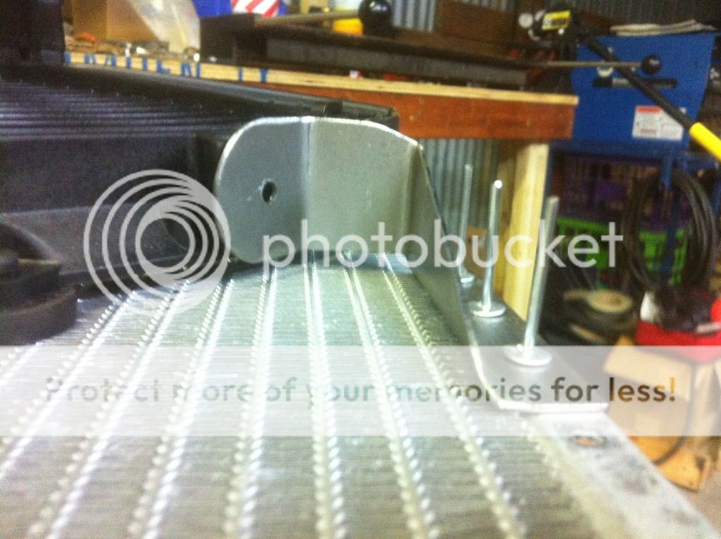
I used some existing brackets to mount the condenser. One on the right and two on the left. I don't know if they used to hold the condenser, or the electric fan. All I had to do was grind off a tiny bit of the length and drill some mounting holes in them. Mounting the fan to the condenser won't be so easy. I need to fabricate some brackets for that. The aluminum is pretty delicate so it's important to not have anything that's going to rub a hole in it. I possibly should have used a puller fan since you could probably fit an 18" one instead of the 16" as a pusher.


Need to push this over to the left a little, I think I'll have to cut an air intake hole right below the original one.

 
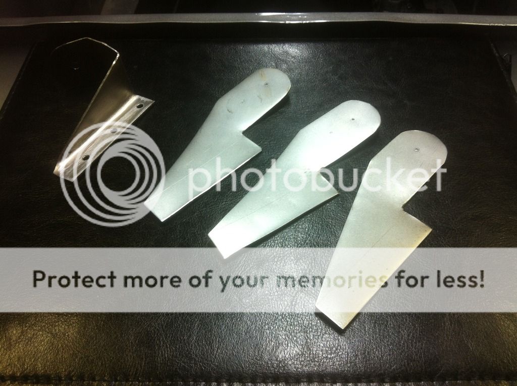
Mounting the electric fan.... BMW electric fans are pretty much exactly like aftermarket ones, they have T-slots in the side for mounting. But unlike the crappy plastic brackets that come with your aftermarket fan and still have nowhere to attach, BMW uses a shoulder bolt and a rubber grommet to mount the fans. You can sort of see here on an E34 http://www.realoem.com/bmw/enUS/showparts?id=HK21-EUR-09-1992-E34-BMW-530i&diagId=64_0132 So I made some brackets today to use those rubber mountings to attach my fan. Just a simple bent piece of steel that is going to pop rivet to the condenser.


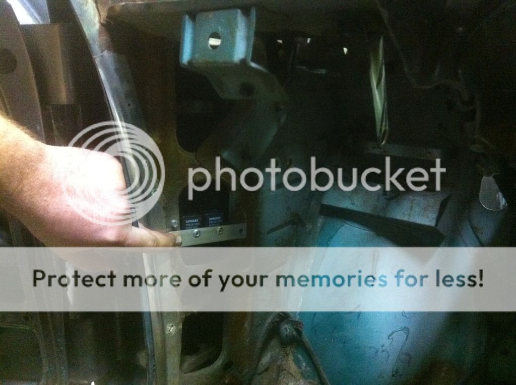
And I worked out where to put my power window relays. These are mounted relay sockets I ordered from Waytech, but you could do the same with the relays that have a mounting tab on them. I just like these better because you can easily remove the relay. I just cut a little aluminum strip and pop riveted the sockets to it using rivet washers. I'll drill holes in the car to rivet the aluminum to. This is all thin enough to stick the vapor barrier over it. For the front windows they mount in the space right in front of the doors. I like this better than mounting them in the doors because you don't need to add another wire through the door jamb, and there's less chance of getting wet in this location. And I don't have my window mechanisms in place yet to know where the unused space is. On the rear there's a similar empty space right in front of the window cavity. Need to cut a slightly longer aluminum strip than what is shown.


Left front:


Right rear:
 
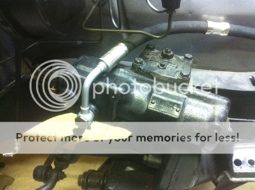
Obviously I'm not the first person to install the newer style power steering pump on one of these, but I don't know what hose everyone else is using. I had a 524td (no hydroboost) hose that would have worked with a little bending on the end, but it was used and a new one is like $300. It's also a little too long. The car came with a new 3.0cs hose, so I wanted to make it work. All I had to do was unsolder a banjo fitting from the 524td hose, cut off the flare fitting from the 3.0cs hose, and silver solder the banjo on. The hose is now swapped end for end from the original position and curves to the side instead of upwards. Perfect for oil filter clearance I think. The heat takes the zinc plating off, so I painted it.


Also finished up all my window relay brackets today.
 
I've always been curious with the newer power steering pumps use. Is the only issue the hoses? Is there a pressure difference or something else that could complicate it or not allow it to work?
 
Should be fine. The old pump is spec'd at 100 bar (1450 psi) and the new one is 110 bar (1600 psi). I can't see how that would make a difference.
 
Back
Top