- Messages
- 292
- Reaction score
- 76
Let's see, what have I been up to?
The differential (3.64 open) felt funny to me. When you turn the flanges opposite directions, you could feel the spiders gear teeth rolling over each other with some pressure. Never saw that on a diff before, didn't seem normal. So I discovered Pete's Gear Shop through this forum, and called him to ask about a rebuild. After I described the problem, he said that's totally normal for these, there is some preload on the spider gears. He agreed it isn't normal for any other diff. Very nice and helpful guy, and his rebuild prices are good. So I took his advice to leave it alone, and instead just put new output shaft seals in it and painted it up.
I also put new boots on the CV axles. I got smart this time and had my local engine shop cut the old boots of and put them in their jet washer so I didn't have to deal with any old grease at all. Still got new grease everywhere, but that's a lot easier to clean up.
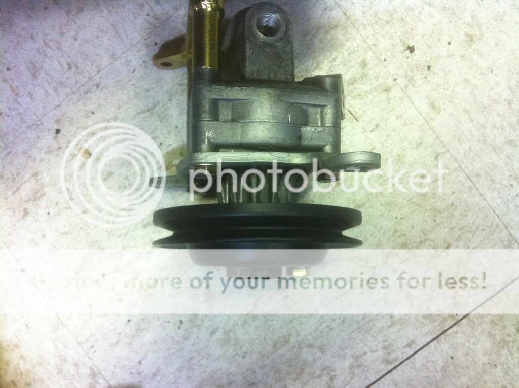
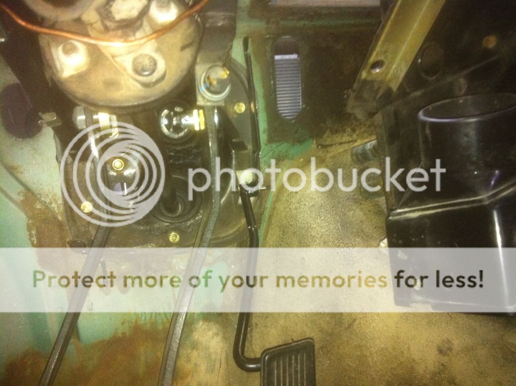
I rebuilt the newer style power steering pump with the kit from BMW. Pretty easy to do, except for removing one little snap ring. It's the kind with no holes in the ends for pliers. Discovered the 524td pulley on the power steering pump I used is not the same as an M30 one. Had the wrong offset. So I managed to find the correct pulley used from a friend.
The wrong pulley. This one fits the diesel as well as M20's.
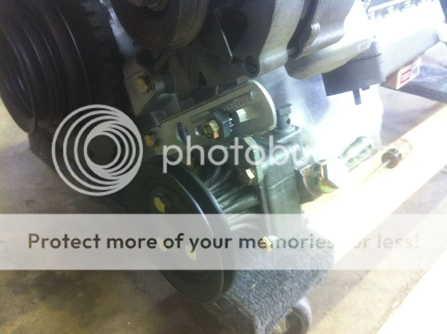
And the right pulley.
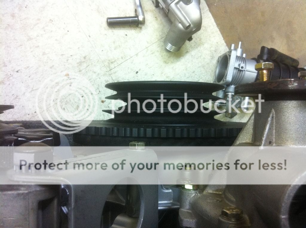
I also discovered that the M30B35 has an overdrive pulley for the AC compressor. I guess to make up for the larger interior volume of the E34 and E32 while using the same old compressor from E30's and E24's? I dunno. But I didn't see any logic in running my AC compressor faster, especially since I went with the Sanden 709 (more flow than the 508) on a car with a very small interior. So I changed that to the M30B34 pulley as well.
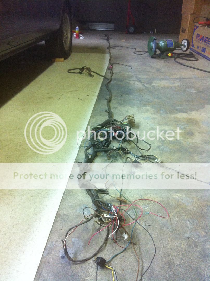
Been doing lots of work on the wiring... I'm going to examine every inch of the harness and redo any suspect connections, fix every previous modification, and add all my new circuits into the old harness before rebundling the whole thing with PET sleeving instead of tape. I learned a couple of useful things... The front end of the harness is actually detachable from the main one. There's a dozen or so spade connectors, one molex connector to the gauge cluster, and a connector to the dimmer switch.
Front and main harness separated
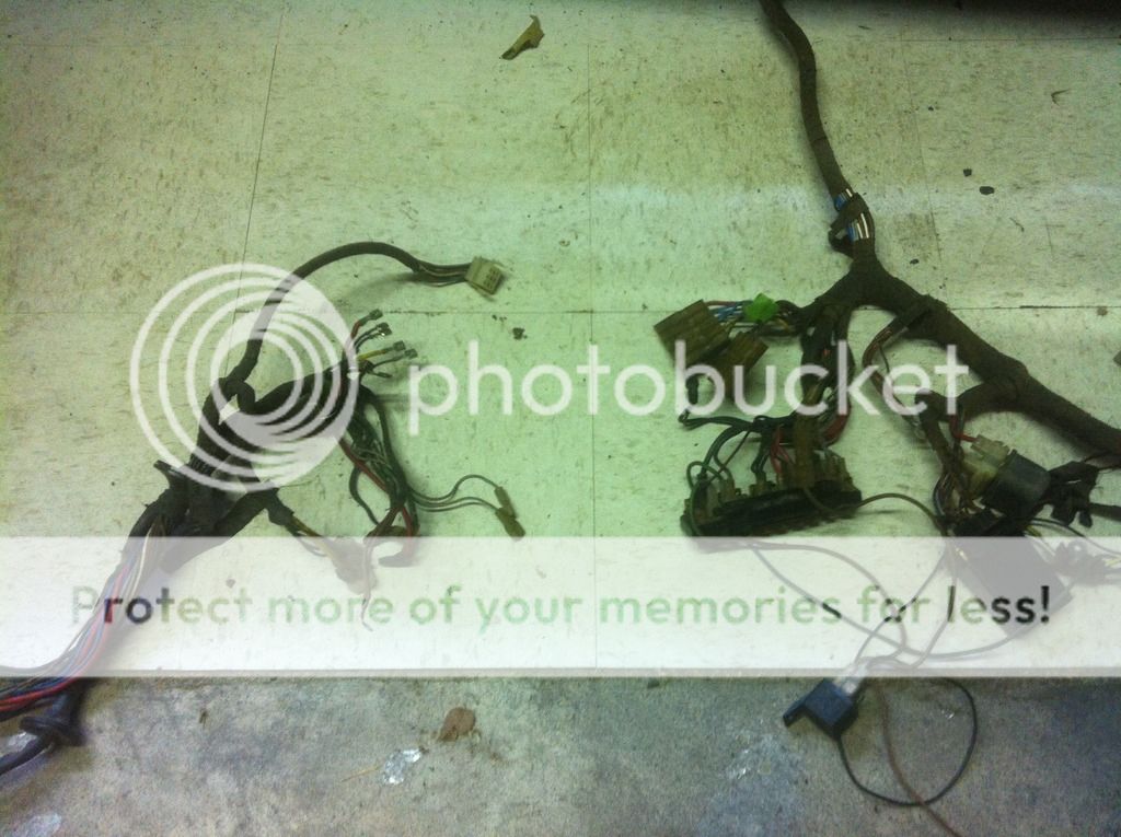
I also learned you CAN remove the entire harness from the car. The part that goes to the trunk goes through some veeeery small holes. At first I thought they must have put the terminals on after it was snaked through. And they might have, but it fit back thorough. Reinstalling it will be interesting. Not as easy to push a rope as to pull one, and I'll have added an extra wire or two.
All stretched out on the floor
Just like unwrapping a 4000 year old mummy
The differential (3.64 open) felt funny to me. When you turn the flanges opposite directions, you could feel the spiders gear teeth rolling over each other with some pressure. Never saw that on a diff before, didn't seem normal. So I discovered Pete's Gear Shop through this forum, and called him to ask about a rebuild. After I described the problem, he said that's totally normal for these, there is some preload on the spider gears. He agreed it isn't normal for any other diff. Very nice and helpful guy, and his rebuild prices are good. So I took his advice to leave it alone, and instead just put new output shaft seals in it and painted it up.
I also put new boots on the CV axles. I got smart this time and had my local engine shop cut the old boots of and put them in their jet washer so I didn't have to deal with any old grease at all. Still got new grease everywhere, but that's a lot easier to clean up.
I rebuilt the newer style power steering pump with the kit from BMW. Pretty easy to do, except for removing one little snap ring. It's the kind with no holes in the ends for pliers. Discovered the 524td pulley on the power steering pump I used is not the same as an M30 one. Had the wrong offset. So I managed to find the correct pulley used from a friend.
The wrong pulley. This one fits the diesel as well as M20's.

And the right pulley.

I also discovered that the M30B35 has an overdrive pulley for the AC compressor. I guess to make up for the larger interior volume of the E34 and E32 while using the same old compressor from E30's and E24's? I dunno. But I didn't see any logic in running my AC compressor faster, especially since I went with the Sanden 709 (more flow than the 508) on a car with a very small interior. So I changed that to the M30B34 pulley as well.

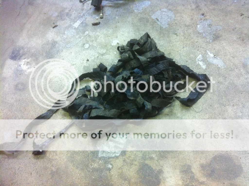
Been doing lots of work on the wiring... I'm going to examine every inch of the harness and redo any suspect connections, fix every previous modification, and add all my new circuits into the old harness before rebundling the whole thing with PET sleeving instead of tape. I learned a couple of useful things... The front end of the harness is actually detachable from the main one. There's a dozen or so spade connectors, one molex connector to the gauge cluster, and a connector to the dimmer switch.
Front and main harness separated

I also learned you CAN remove the entire harness from the car. The part that goes to the trunk goes through some veeeery small holes. At first I thought they must have put the terminals on after it was snaked through. And they might have, but it fit back thorough. Reinstalling it will be interesting. Not as easy to push a rope as to pull one, and I'll have added an extra wire or two.
All stretched out on the floor

Just like unwrapping a 4000 year old mummy


")


