A/C Wiring Diagram for 1975 CSi – Need Help

LEO

Active Member
Site Donor
Messages
74
Reaction score
12
Location
BOGOTA COLOMBIA
Hi everyone, I just want to take a moment to wish you all a Merry Christmas and happy holidays with your loved ones. On my side, I’m super happy — today I finally got the engine back in place after months of restoring the wiring harnesses.

However, I’ve run into an issue with the A/C installation on my cSI model 75. I haven’t been able to find a wiring diagram specific to the model 75, and I’m a bit stuck. Does anyone here have that wiring diagram or any info that might shed some light on this?

Thanks and best regards!


WhatsApp Image 2025-12-23 at 18.47.26.jpeg
 
Thanks, but in my car the wire colors are very different. I’m not sure if this is due to it being a 1975 model. I’ll try to sketch out a diagram myself and see if that helps shed some light on how to connect everything. :(
 
The GN-BR wire shown in the diagram you sent goes to fuse #4 and comes from thermoswitch #7.
In my case, I see it in my car’s wiring diagram going to fuse #10, and it matches the wire colors in my fuse box.
However, I can’t find device 22 with actual wiring — it only shows SW.
From device 24, I also don’t have that SW wire.
And finally (which I think is the easiest part), I don’t have the RT wire that goes from the relay to the battery with an inline fuse, so I think I’ll have to make it myself.
Does anyone know what amperage that fuse should be?


Thanks and greetings!
 

Attachments

  • Screenshot 2025-12-26 at 12.01.45 PM.png
    Screenshot 2025-12-26 at 12.01.45 PM.png
    174.1 KB · Views: 49
  • Screenshot 2025-12-26 at 12.01.33 PM.png
    Screenshot 2025-12-26 at 12.01.33 PM.png
    376.7 KB · Views: 42
On a pre-74/75 the relay #9 for the condenser fan is mounted below the coil, yours might be near the battery and uses a 25 amp fuse. Also, you might not have the thermo switch attached to your radiator which is another 74 feature, it turns on the fan without using the a/c. Do you have the factory a/c console or is yours aftermarket like we see in Italian delivery coupes?
 
  • Like
Reactions: LEO
You’re really shedding light on this, and now everything makes sense. The relay is indeed next to the battery, and I do have the original factory console. Thanks a million!!! I believe I do have a thermo switch installed in the radiator as well. Am I interpreting the diagram correctly that the wire goes to fuse #10?
 
Additionally, from the thermo switch (which should be #7 in the diagram), I have the SW-WS wire going directly to the compressor (#23). Would the diode (#20) be inside the compressor, or could it have been removed during disassembly?
Also, I don’t seem to have terminal #21 in my wiring (which is where I mentioned I don’t have any SW wires).
Sorry for so many questions and for being so intense about this. Thanks!!!
 
The diode goes between the auxiliary fan relay and the compressor.

When the AC is turned on the compressor operates and the auxiliary fan operates.

When the engine temperature sensor closes- the auxiliary fan operates but the AC does not engage.

We use a BMW diode or you can use a relay with a built in diode.

http://www.bmwbuddy.com/z/part/61311358268-bmw-auxiliary-fan-diode

English translation of components may help you.

1 battery
2 load shed relay
3 fuse
4 Ground
5
6
7 temperature switch
8 connector
9 fan relay
10 auxiliary fan
11 ignition
12 connector
13 blower switch
14 heater blower
17 resistor
18 air conditioning fan motor
19 ac/auxiliary fan connection
20 diode
22 temperature control switch
23 compressor
24 ac fan speed
 

Attachments

  • IMG_3328.png
    IMG_3328.png
    1.5 MB · Views: 48
  • Like
Reactions: LEO
Maybe look at other schematic?
 

Attachments

  • IMG_3329.png
    IMG_3329.png
    1.6 MB · Views: 52
  • Like
Reactions: LEO
Is the AC wiring harness separate from the main harness?
Or do cars that came with factory-installed AC have a different harness than those that didn't?
 
Wiring diagram for a/c is separate, 73 and earlier is different from 74/75 as you know. Harness is the same for all and the main harness changed in 09/73 for MY 74. Coupes shipped to the US and I presume all other countries had the a/c components in the trunk and it was installed by the dealer.
 
After checking every single wire and finding some important differences compared to the closest wiring diagram, “Schaltplan der Klimaanlage (ab Modell 73)”, I suspect that some variations apply to the well-known ’73 ½ and later models.

Yesterday, we had a video call with @alprada70 , during which we identified and clarified several points. I’d like to document everything here so that if someone runs into the same situation, this information can be helpful.

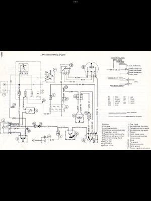
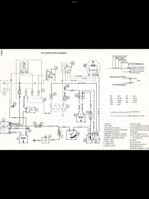
First, I am using this wiring diagram along with the translation that @sfdon kindly shared with me, which has been extremely helpful. One important clarification: when the car is equipped with A/C, there are additional wiring harnesses (at least in my case).

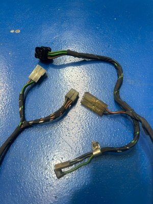
I’m attaching a photo of these harnesses for documentation purposes:

One internal harness, shown in one of the photos.

A second external harness, which is already integrated into the taped main harness.

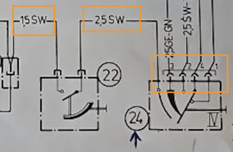
The internal harness connects to connectors 12 and 15 in the diagram. Part of the confusion initially came from not realizing that these connectors are 3-wire connectors. Once that became clear, it was easier to understand the wiring path between the Temperature Control Switch (#22) (black wire) and connector #21, where another black wire comes from the diode (#20).

That diode was unfortunately lost or removed by mistake during disassembly, likely because we assumed it was uncommon to have only black wires in the harness. We later had to restore it and add it back correctly.

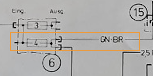
As I had mentioned before, regarding #6 (the fuse box): in my car, the GN-BR wires go to fuse #10, not fuse #4 as shown in the diagram. This is another difference worth noting for anyone using this schematic as a reference.

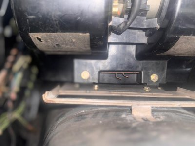
After all these findings, I’m also attaching a photo showing the A/C blower. Underneath it, there appear to be two connectors. Could this be device #17 (resistor) in the diagram? I’d appreciate it if someone could confirm this.

Thanks in advance, and I hope this helps others working through similar wiring issues.
 

Attachments

  • AC_WIRING_DIAGRAM.pdf
    AC_WIRING_DIAGRAM.pdf
    1.3 MB · Views: 6
  • WhatsApp Image 2026-01-23 at 08.34.57.jpeg
    WhatsApp Image 2026-01-23 at 08.34.57.jpeg
    332.4 KB · Views: 9
  • WhatsApp Image 2026-01-23 at 08.34.56.jpeg
    WhatsApp Image 2026-01-23 at 08.34.56.jpeg
    366.4 KB · Views: 12
  • WhatsApp Image 2026-01-23 at 10.27.44.jpeg
    WhatsApp Image 2026-01-23 at 10.27.44.jpeg
    93.4 KB · Views: 10
The picture you show from the evaporator box shows the built-in resistor, which is used in combination with the blower switch to regulate the blower motor speed. When you look at it from the inside the box it shows a resistor coil.

1769191858012.png
 
Everything that is in the main harness is in red.
Where does the GN-BR wire go? Because that color wire goes to fuse 10, and wires 93 and 97 are already connected there.
 
  • Like
Reactions: LEO
Back
Top