Best Lift Points

TG-2002-320i-328ci

Well-Known Member
Site Donor $
Messages
176
Reaction score
41
Location
Tucson, AZ
I've searched the forum and this topic has come up but the threads are mostly old with missing or low-res "photobucket" photos.

I have access to a four-point hydraulic lift and was wonder what are the best front and rear points?

My rockers are tenuous, at best, so the original jack points are a non-starter.

Thank you
 

Honolulu

Well-Known Member
Messages
1,918
Reaction score
226
Location
Honolulu Hawaii
Back in the day I used a generic scissor jack from a generic Japanese auto... until 1) I saw it start to give one day and 2) my wife got be a proper trolley jack. Mortal of the story: not all scissor jacks are up to the task. Yeah yeah, "mortal" vs "moral" but I think the point is made either way. I haven't killed myself yet but not for lack of trying.
 

bavbob

Well-Known Member
Site Donor
Messages
3,354
Reaction score
1,569
Location
Boston, Ma
I use the subframe on the front. I have 2 e24s and an e3 and the rails are crushed at points where the car was lifted...by the PO's. Doesn't the rail undercoating get cracked etc also?
 

Stevehose

Well-Known Member
Site Donor $$
Messages
12,934
Reaction score
5,598
Location
Sarasota, FL
Yes it does, I always reapply undercoat at the frame jack spots when back on the ground

I use the subframe on the front. I have 2 e24s and an e3 and the rails are crushed at points where the car was lifted...by the PO's. Doesn't the rail undercoating get cracked etc also?
 

JamesE30

Well-Known Member
Messages
345
Reaction score
413
Location
Germany
I use the subframe on the front. I have 2 e24s and an e3 and the rails are crushed at points where the car was lifted...by the PO's. Doesn't the rail undercoating get cracked etc also?

This post is quite timely, since I’m in the middle of a bare metal rebuild and i was wondering..

Has anybody welded reinforcements to the frame rail or another area to be specifically used as an obvious lifting point?

I was wondering if there would be a clean way to retrofitnew model factory bmw lift points with consumable screw on plastic blocks..

I see so many old cars damaged over the years by incorrect or careless lifting (sometimes through no fault of the owner but various careless workshops)

It would certainly put my mind at ease knowing I have a safe/strong/obvious point under the car that won’t damage it..

Just a thought..


804F1E95-C42F-435B-9083-4054A3DFE523.jpeg
 

bavbob

Well-Known Member
Site Donor
Messages
3,354
Reaction score
1,569
Location
Boston, Ma
I gave one of those poly biscuits to the shop that inspects all my cars. Here in MA, they all have to be lifted to check the front end. I love those things and at 5 bucks or so, bargain.
 

rsporsche

Moderator
Site Donor $$
Messages
10,634
Reaction score
3,671
Location
Atlanta, GA
Would love to know what you settle on, as far as a scissor jack is concerned...thanks.
will do Dave ... i agree that all scissor jacks are not created equally ... and i only intend to use one in an emergency when on the road. i have a wonderful low profile jack for use in the garage
 

eriknetherlands

Moderator
Site Donor
Messages
2,699
Reaction score
1,930
Location
Netherlands, Eindhoven area
I do use the framerails as a lift point on the front end, (engine still in, auto gearbox out), without damage. For this i use a thick rubber block that is generously wider then the frame rails; its about 15x15x4 cm, about 7x7x1,5 inch. It's all about spreading the load. As first contact layer i use a t shirt.

20180131_105640.jpg

No e9's were harmed during this lifting.

Regarding reinforcements; if you replace the front floors, then you can choose to remove the section that closes the frame rails, allowing access to the inside of the rails, and you can hammer/plannish the dents back.

You could weld in some stiffening ribs inside the frame rails, but it will make it harder to treat the insides adequately with rust preventative wax/paint whatever. And you cant really clean the welds well prior to sealing them So i have chosen to leave it all as per 'factory' design and to lift carefully in the future.
 

Attachments

  • 20181031_231113.jpg
    20181031_231113.jpg
    211.8 KB · Views: 276
  • 20181116_003908.jpg
    20181116_003908.jpg
    194.5 KB · Views: 287
  • 20181116_004227.jpg
    20181116_004227.jpg
    240.8 KB · Views: 265
  • 20180131_111827.jpg
    20180131_111827.jpg
    208.6 KB · Views: 294
Last edited:

eriknetherlands

Moderator
Site Donor
Messages
2,699
Reaction score
1,930
Location
Netherlands, Eindhoven area
In the rear the best place to lift is at the rear axle, either the sub frame, or it's mounting points.
I prefer the rear subframe bushing mounts; the thick M14 bolt vertically under the seats. I dig up this pic from another thread; notice the yellow lift arm . ( ignore the drawn arrow) (https://www.e9coupe.com/forum/threads/hoist-lifting-points.10049/#post-69432):
JackPoint.jpg


I've also used a wooden block under the differential mount:
20190421_145856.jpg


Even just a piece of wood, on only one layer of the sill, but only with an empty shell:
20180120_213315.jpg
20180121_230612.jpg
20180313_233800.jpg


I did weld in reinforcements at the front jack points while I replaced the inner sills. I won't be using them, but if someone would, they will hold.
20180411_220917_intermediate sill front jacking point reinforcement.jpg 20180411_220834 intermediate sill jacking point reinforcement.jpg
 
Last edited:

autokunst

Well-Known Member
Site Donor $$
Messages
3,606
Reaction score
2,619
Location
Milwaukee, WI
This is a great topic - one that clearly affects all of our coupes. Right after my coupe was delivered, I had a local shop put it on the lift where it sat up for several days. I wasn't sure where they supported it, but just checked my photos. It looks like they used extra wide rubber faced lift pads. In the rear, the lift pad was under the rocker jack point and also picked up a bit of the rear subframe arm - so a dual approach. In the front, they had it on the rocker again, and also under the floor panel. It seems to have survived, but I look forward to opening up the rockers and may consider some additional support as @eriknetherlands shows - that looks really well done!
 

JayWltrs

Well-Known Member
Site Donor $
Messages
954
Reaction score
534
Location
Oklahoma City
I did weld in reinforcements at the front jack points while I replaced the inner sills. I won't be using them, but if someone would, they will hold.
View attachment 81948 View attachment 81949

Erik, Impressive as usual. I don't think I could bend 1 piece to come out that well w/o alot more equipment. How many pieces of metal did you use for the support? Did you weld the back support and feet on separately? Thanks
 

eriknetherlands

Moderator
Site Donor
Messages
2,699
Reaction score
1,930
Location
Netherlands, Eindhoven area
quote from autokunst: "In the rear, the lift pad was under the rocker jack point and also picked up a bit of the rear subframe arm - so a dual approach".

Be carefull lifting it your car by the rockers/ sills! Likely we can spot exactly where your shop lifted your car...

In OEM condition, the rockers are made of multiple layers, including the outer decorative cover on them. Both the outer sill (structural&welded) and the decorative cover (screwed on) stick out BELOW the inner sill. If you try to lift the car by putting something under the flange , then the first thing that happens before your coupe is raised, is that you'll sqaush your outer sill & rocker cover into the inner sill.

See the pics:
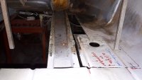
First pic shows how the rear left subframe mounting point. The sill construction is a bit vague, but you can just see the white inner sill, and the yellow zinced outer rear quarter panel /skin. This yellow part curves under and around the white vertical flange. Also the drain hole see here makes this curve.
20190411_000327.jpg
20190411_000650.jpg

On all 4 corners of the sill, it has this construction; the 4 quarter panels contain this curvature on the bottom.

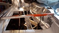
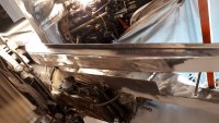
Below the door, there are no quarter panels, so the outer structural sill that has this curve feature. In the pic below you're looking at the right sill & A-pillar just . Notice how on the left the flange is part of the outer structural, welded sill, and how it tucks under the body. Just right of the jack point, the panel ends. This is where the front quarter panel should meet up. See the ~5 mm (1/4inch) difference in height comparing the flange left and right of the jack point ?
20171223_024133.jpg


Now, having explained how the sills are constructed, you can image what happens if you place something under this flange: The flange will be pushed up 5mm (1/4 inch) until it touches the 2 inner sill layers. Perhaps even closing the drain holes if it's a bad day.

I've seen plenty of the pinch marks in for sale threads. let me see if I can dig some up...
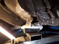
Edit: here you go. Something went wrong with this sill. Notice the flange line isn't straight anymore? (ignore the offset of the pickup point & the opening in the decorative sill )
1574243158272.png
 
Last edited:

eriknetherlands

Moderator
Site Donor
Messages
2,699
Reaction score
1,930
Location
Netherlands, Eindhoven area
Erik, Impressive as usual. I don't think I could bend 1 piece to come out that well w/o alot more equipment. How many pieces of metal did you use for the support? Did you weld the back support and feet on separately? Thanks

It is not at all difficult, no welding, just folding. If you would weld it together from multiple sections, you just end up with a lot of welds to grind. It'll never be as straight compared to just folding.

All I have is a piece of paper & scissors to make a paper template. Paper is easy to shape, and no-one will ever know if you needed 4 tries to get it right.
Then trace the paper template on a steel plate, marking not only the contours, but also the bending lines. Chop away with a grinder.
Then it is onto the vice and a soft hammer. Rubber, plastic, aluminium, copper: all will work. Steel hammers leave smash marks.
In the vice I use something to prevent 'bite marks' on my workpiece from the teeth of the vice surfaces . 2 sections of aluminium work well.

To control the bending radius, I insert an extra steel plate behind the bending line which I gave a nice smooth edge with a grinder. This forces your work piece to follow the radius and not develop a tighter radius.

I do not have pics of the paper shape, but here's the still flat part, in the first pic, on the right,. The left thing is the strange shape under the floor at the front left wheel, where the Floor meets the A-pillar & wheel well.
IMG-20180402-WA0003_resized.jpeg
20180411_220750.jpg
20180525_212140.jpg


20180411_225046.jpg
20190411_001645.jpg
 

autokunst

Well-Known Member
Site Donor $$
Messages
3,606
Reaction score
2,619
Location
Milwaukee, WI
Be carefull lifting it your car by the rockers/ sills! Likely we can spot exactly where your shop lifted your car...
Erik, first of all, I LOVE, LOVE, LOVE seeing your amazing metal work. It inspires me - thank you!

Upon inspection, the bad news is that I see the front pick point on my rockers has a little bit of deformation (the squashing). Not sure if it was there prior to my shop's lift or not. The good news is that the rear point doesn't seem to exhibit the same. Maybe their pad was really more in contact with the rear subframe. But more good news - the rockers didn't just collapse under the weight of the car! I plan to completely reconstruction the car - much like you are. So I am very pleased that aspects of the chassis seem reasonably intact such that I can address areas with new metal systematically.

Thanks again for your great imagery! These are in no small way my guide.
 

Stevehose

Well-Known Member
Site Donor $$
Messages
12,934
Reaction score
5,598
Location
Sarasota, FL
The Oldenzaal pic showing the rear lift point looks too inboard for my liking, I put a piece of wood over the rear subframe mount bolt which spreads the load over the ridged piece that bolts over it. This pic looks like it's on only one of the ridges.
 
Top