BMW E9 Auto to 5SPD manual Conversion

nobrakese28

Well-Known Member
Messages
207
Reaction score
12
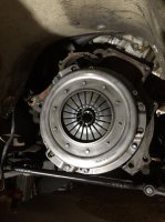
Hi. I thought I would document the 5SPD manual conversion I am performing on my 1971 BMW 2800CS. This is intended as a reference only, please only work on you vehicle if you are confident and able, I assume no responsibility for anyones actions.

BMW Parts:
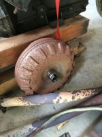
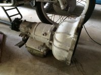
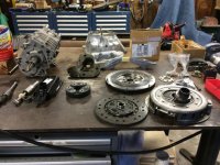
Transmission: Getrag 265 5SPD
Transmission Mounting Bracket: 23711175731
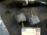
Transmission Mounts:
Transmission Tower Shift Mounts:
Shifter Mounting Plate:
E28 M5 Guibo: 30mm thick: 26117511454
Driveshaft: E9 2800CS Auto Transmission Driveshaft lengthened 1.6 inches (could possibly be a 1978 530i driveshaft, they may be the same)
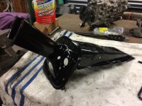
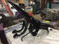
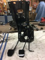
Pedal Box: Pedals from any manual, use what ever pedal box you have in your car.
Clutch Line: La Jolla Independent
Clutch Slave:
Clutch Master:
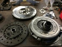
Clutch Kit: E28 533i/535i
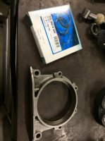
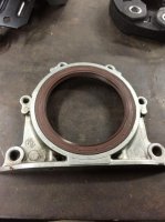
Rear Main Seal:
Rear Main Seal Housing Gasket:
Starter: (good idea to replace with the E30 M3 if you have a stock unit, the E30 M3 is much more compact and easy to install)
Exhaust Manifold Gaskets:

Fasteners:
Flywheel bolts:
Pressure Plate Bolts:


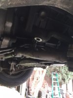
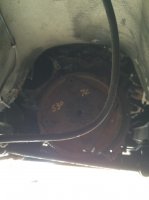
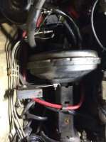
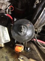
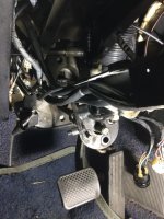
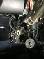
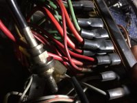
1) The first thing I did was securely place the CS on my Mohawk, I took a look at the car and verified that I wanted to start the job. This isn't a quick 8 hour job, there are a lot of parts that need to removed and replaced. Then I removed the battery from the engine bay. This is important as you will be removing the starter.

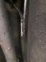
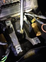
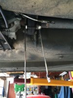
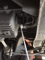
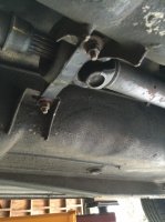
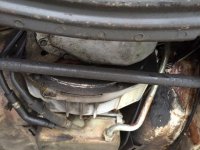
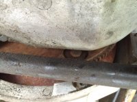
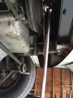
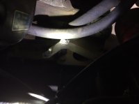
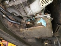
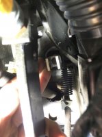
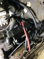
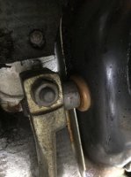
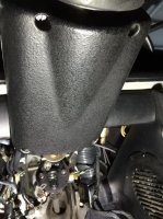
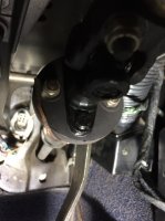
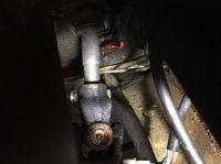
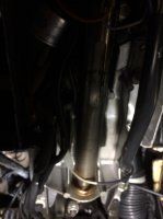
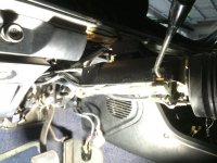
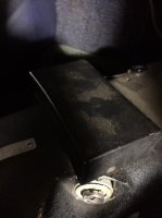
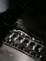
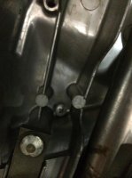
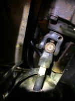
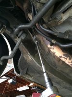
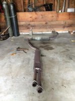
1a) The first thing I did was remove the center portion of the exhaust, watch your knuckles as the bolts are likely rusty. There is a 90% chance that the exhaust will not slip off from the slip fit, if it doesn't. First remove the 6 bolts from the flanges, then have an assistant support the muffler while you remove the 3 bolts holding the rubber hangers, don't balance it over your shoulder's like I did...

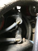
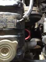
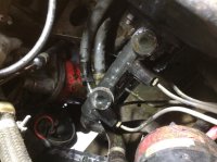
2) Remove down pipes, 6 bolts.

See photos.
 

Attachments

  • thumb_IMG_2992_1024.jpg
    thumb_IMG_2992_1024.jpg
    90.8 KB · Views: 654
  • thumb_IMG_2991_1024.jpg
    thumb_IMG_2991_1024.jpg
    89.7 KB · Views: 585
Last edited:
3) Next I decided to remove the shift console, start my unscrewing your shift knob, then remove the window switches. Take note of the wiring, I find photos work great.

When you remove the two rear window switches you will reveal a screw on each side, these two screws hold the console down. Remove them, this will let you move it up so you can get to the cigarette lighter an wiper wiring.

4) Time to start working under the dash. Remove the screw holding the hood release lever hanger, then remove the trip meter set screw. Do this by loosening the set screw on the knob, then remove the collar nut, you will need pliers for this. The under dash kick panel will need to come out, there are a few screws holding this in. Careful with the hazard and defrost switch.
 

Attachments

  • thumb_IMG_3004_1024.jpg
    thumb_IMG_3004_1024.jpg
    88.2 KB · Views: 482
  • thumb_IMG_3002_1024.jpg
    thumb_IMG_3002_1024.jpg
    49.7 KB · Views: 553
  • thumb_IMG_3001_1024.jpg
    thumb_IMG_3001_1024.jpg
    77.3 KB · Views: 466
  • thumb_IMG_3003_1024.jpg
    thumb_IMG_3003_1024.jpg
    46 KB · Views: 456
Last edited:
5) Go back to shifter area, remove the four screw holding the plastic plate onto the shift mechanism, then go under the car and pop the clip from the shift linkage, then go back into the car and remove the three bolts holding the shift mechanism. Remove shift mechanism.
 

Attachments

  • thumb_IMG_3009_1024.jpg
    thumb_IMG_3009_1024.jpg
    84 KB · Views: 433
  • thumb_IMG_3012_1024.jpg
    thumb_IMG_3012_1024.jpg
    80.7 KB · Views: 437
  • thumb_IMG_3015_1024.jpg
    thumb_IMG_3015_1024.jpg
    91.9 KB · Views: 457
6) Driveshaft removal. Remove the bolts holding the guibo to drive shaft, then remove the nuts holding the tail to the diff, you can use a screw driver to react the torque. Then remove nuts holding center support bearing, remove driveshaft.
 

Attachments

  • thumb_IMG_3018_1024.jpg
    thumb_IMG_3018_1024.jpg
    89.8 KB · Views: 450
  • thumb_IMG_3019_1024.jpg
    thumb_IMG_3019_1024.jpg
    66.7 KB · Views: 451
  • thumb_IMG_3020_1024.jpg
    thumb_IMG_3020_1024.jpg
    90.2 KB · Views: 445
7) Remove the flywheel/flexplate cover, this will allow you access to the torque converter. I used a breaker bar on the crankshaft to react the torque on the flex plate. Remove the four bolts.

8 ) Remove the draglink to idler arm nut, you may need a ball joint separator to pop the link out of the taper. Doing this will allow the trans to drop an extra inch.
 

Attachments

  • thumb_IMG_3021_1024.jpg
    thumb_IMG_3021_1024.jpg
    90.8 KB · Views: 421
  • thumb_IMG_3022_1024.jpg
    thumb_IMG_3022_1024.jpg
    92.6 KB · Views: 431
  • thumb_IMG_3023_1024.jpg
    thumb_IMG_3023_1024.jpg
    88.1 KB · Views: 431
  • thumb_IMG_3029_1024.jpg
    thumb_IMG_3029_1024.jpg
    66.3 KB · Views: 441
Last edited:
9) Time to remove the starter, this by far took the longest. Maybe because I have the original large body starter. Remove the air cleaner to gain some access . I used a long snap-on straight wrench, the lack of angle in the wrench allowed me fit in the narrow access area. You will need to remove the throttle linkage and pivot to remove the starter from the engine bay. Don't forget to remove the three wires going to the starter.

10) Remove the kick down cable bracket.
 

Attachments

  • thumb_IMG_3024_1024.jpg
    thumb_IMG_3024_1024.jpg
    91.1 KB · Views: 458
  • thumb_IMG_3025_1024.jpg
    thumb_IMG_3025_1024.jpg
    65.6 KB · Views: 442
  • thumb_IMG_3027_1024.jpg
    thumb_IMG_3027_1024.jpg
    53.3 KB · Views: 424
  • thumb_IMG_3028_1024.jpg
    thumb_IMG_3028_1024.jpg
    42.9 KB · Views: 435
Last edited:
11) Drain the transmission and remove the lines, consider doing this the night before.

12) Remove the trans mount bracket bolts, this will drop the trans so you can access the bolts securing it to the bell housing.

13) Removing tranny, remove the bolts securing the trans to the engine, caution!! As soon as bolts are removed the trans can fall out and kill you. I placed a jack under the transmission pan, once the bolts were removed the tranny slid out. Note if you have a auto, a lot of oil is about to poor from the torque converter, so be ready to catch it. I used a pry bay to walk the trans out. Once the trans is out you can you can remove the torque converter, it should slide out.

It got hard for me to capture photos at this point, as I was working solo.
 

Attachments

  • thumb_IMG_3030_1024.jpg
    thumb_IMG_3030_1024.jpg
    91.6 KB · Views: 478
  • thumb_IMG_3031_1024.jpg
    thumb_IMG_3031_1024.jpg
    91.4 KB · Views: 465
  • thumb_IMG_3032_1024.jpg
    thumb_IMG_3032_1024.jpg
    89.8 KB · Views: 468
  • thumb_IMG_3033_1024.jpg
    thumb_IMG_3033_1024.jpg
    42.9 KB · Views: 465
##############PLEASE NOTE, THE PEDAL BOX DOES NOT NEED TO BE REMOVED TO ADD THE CLUTCH PEDAL, I DID THIS BY MISTAKE, BUT IT ALLOWS ME TO POWDER COAT PEDAL BOX AND PEDALS###########

14) At this point you will have to begin the pre-work to removing the pedal box, I recommend taking lots of photos of all the connectors you disconnect.

If you have an auto, where the clutch master would be located on a manual is a wire bracket. You will have to remove two bolts.
 
Last edited:
15) In order to remove the pedal box you will have to remove the brake master cylinder and booster. Please be aware that brake fluid is really corrosive and will eat paint if not removed in a timely fashion.

Start by removing the draining the master cylinder reservoir, then remove it. Just give the lines a tug at the master cylinder.

Next remove the water reservoir, I recommend placing a tun underneath to catch the coolant.

Then remove the 5 brake lines, then the two nuts holding the master two the booster. Clean and place the master cylinder in a zip-lock bag.

Remove the bracket bracing the booster to the fender. Then remove the 2 remaining bolts, this will free the booster. But you will have to pop the clip on the boosters linkage to the brake pedal. This will completely liberate the booster. Before you can remove it, remove the bolts holding the power steering reservoir, this will give you the additional clearance needed to maneuver the booster out.
 

Attachments

  • thumb_IMG_3041_1024.jpg
    thumb_IMG_3041_1024.jpg
    68.5 KB · Views: 438
  • thumb_IMG_3042_1024.jpg
    thumb_IMG_3042_1024.jpg
    87.3 KB · Views: 413
  • thumb_IMG_3046_1024.jpg
    thumb_IMG_3046_1024.jpg
    83.9 KB · Views: 472
  • thumb_IMG_3047_1024.jpg
    thumb_IMG_3047_1024.jpg
    82.1 KB · Views: 436
  • thumb_IMG_3049_1024.jpg
    thumb_IMG_3049_1024.jpg
    66.1 KB · Views: 416
  • thumb_IMG_3050_1024.jpg
    thumb_IMG_3050_1024.jpg
    89.6 KB · Views: 368
  • thumb_IMG_3051_1024.jpg
    thumb_IMG_3051_1024.jpg
    93.7 KB · Views: 399
16) In Order to remove the pedal box, it will have to pull through the interior, so you'll have to remove the throttle arm. I used a drill point punch to mark the arm and tube to retain the clocking.
 

Attachments

  • thumb_IMG_3057_1024.jpg
    thumb_IMG_3057_1024.jpg
    81 KB · Views: 378
16) Important, center the wheels. Next use a punch to leave witness marks on both sides of the coupler and also the steering box and steering shaft. Remove both bolts from coupler, so which ever wants to slide first does.

17) Back to under the wheel, remove the four nuts on the steering donut, technically you only have to remove the pair, but I found out its best to let release from whichever it prefers naturally.

18) Remove the four screws fastening the aluminum cover under the steering column.

19) There are six screws holding the steering column to the pedal box, once you remove these screws the column will drop so be ready.

TIP: Slide the seat forward, the steering wheel will rest on the seat allowing you to work.

20) Remove six bolts, slide seat to support column, separate the steering column from the steering shaft via the donut.

21) The steering shaft should slide off the steering box, if not help it off the shaft.

22) Remove clip on gas pedal rod, remove rod from pedal.

23) Remove brake light switch wires.

23) Remove the six screws fastening the pedal box to the firewall.

24) Remove two screws fastening the pedal box, these were hidden by the steering column.

25) Carefully pull the pedal assembly out, move the steering column to the left side of the footwell.
 

Attachments

  • thumb_IMG_3061_1024.jpg
    thumb_IMG_3061_1024.jpg
    93.8 KB · Views: 393
  • thumb_IMG_3060_1024.jpg
    thumb_IMG_3060_1024.jpg
    67.3 KB · Views: 386
  • thumb_IMG_3058_1024.jpg
    thumb_IMG_3058_1024.jpg
    60.7 KB · Views: 404
  • thumb_IMG_3062_1024.jpg
    thumb_IMG_3062_1024.jpg
    49.1 KB · Views: 387
  • thumb_IMG_3064_1024.jpg
    thumb_IMG_3064_1024.jpg
    86.6 KB · Views: 380
  • thumb_IMG_3065_1024.jpg
    thumb_IMG_3065_1024.jpg
    91.9 KB · Views: 375
  • thumb_IMG_3066_1024.jpg
    thumb_IMG_3066_1024.jpg
    89.5 KB · Views: 383
  • thumb_IMG_3067_1024.jpg
    thumb_IMG_3067_1024.jpg
    91.8 KB · Views: 399
26) Removing the flex plate, have a buddy place a 36mm socket on the crankshaft to react the large amount of torque you are about to apply to the 8 bolts. Once the bolts are out, use a pry bar to un-wedge the flex plate.

27) If you have an auto, the next step isn't fun. There is a press fit bushing that needs to be removed from the crankshaft. Use a quality puller and slide hammer, the job required both. You don't want to botch this up, it will get real expensive.
 

Attachments

  • thumb_IMG_3084_1024.jpg
    thumb_IMG_3084_1024.jpg
    64.2 KB · Views: 408
  • thumb_IMG_3085_1024.jpg
    thumb_IMG_3085_1024.jpg
    92.7 KB · Views: 398
  • thumb_IMG_3086_1024.jpg
    thumb_IMG_3086_1024.jpg
    95.1 KB · Views: 413
Last edited:
28 ) Pedal box. I used my original box with the pedals out of a 1974 3.0CS. The pedals dropped right but the clutch pedal had to be modified, simply cut the lug off the clutch pedal. The clutch pedal return spring uses the same exact system as the brake pedal
 

Attachments

  • thumb_IMG_3102_1024.jpg
    thumb_IMG_3102_1024.jpg
    93.5 KB · Views: 403
  • thumb_IMG_3109_1024.jpg
    thumb_IMG_3109_1024.jpg
    93.4 KB · Views: 414
  • thumb_IMG_3105_1024.jpg
    thumb_IMG_3105_1024.jpg
    91.7 KB · Views: 405
  • thumb_IMG_3104_1024.jpg
    thumb_IMG_3104_1024.jpg
    88.2 KB · Views: 393
29) Time to remove the shift indicator lamp. Remove the two side screws, the cover will come off. This will expose the wired and bulbs.

Flip the steering column to gain access to the two screws, this will free the shift indicator lamp box. I decided to cut the wire, they are soldered to the shift indicator lamp and there is a connector on the other side. The connector should already be disconnected, its probably possible to free the pins from the connector.
 

Attachments

  • thumb_IMG_3110_1024.jpg
    thumb_IMG_3110_1024.jpg
    60.3 KB · Views: 374
  • thumb_IMG_3111_1024.jpg
    thumb_IMG_3111_1024.jpg
    78.2 KB · Views: 371
  • thumb_IMG_3112_1024.jpg
    thumb_IMG_3112_1024.jpg
    70.7 KB · Views: 348
30) Move the steering column to the side, slide the pedal assembly into place. Loosely attach the four screws with the large washers then replace the pedal box to the footwell using the six screws. Tighten them all up.

Install the steering shaft, line up your marks on the box, shaft, and coupler. I then torques the screw holding the coupler to the steering box. Leave the connector between shaft and couple loose for now.

Replace the steering column using the four screws, have an assistant support the steering wheel while you line the quibo to the studs, make sure the ground wire is in.

Tighten up the four nuts on the guibo, if the guibo is stretched when the nuts are tight push the steering shaft with a screw driver reacting against the coupler. Once the guibo is in a natural state, tighten the coupler.

Go back and tighten couple. Ensure all steering components are fastened.
 

Attachments

  • thumb_IMG_3116_1024.jpg
    thumb_IMG_3116_1024.jpg
    69.9 KB · Views: 364
  • thumb_IMG_3117_1024.jpg
    thumb_IMG_3117_1024.jpg
    68.2 KB · Views: 367
  • thumb_IMG_3115_1024.jpg
    thumb_IMG_3115_1024.jpg
    88.4 KB · Views: 396
  • thumb_IMG_3119_1024.jpg
    thumb_IMG_3119_1024.jpg
    75.6 KB · Views: 364
Last edited:
Wow!

Outstanding work & documentation. I had mine done last year professionally, I envy those who can do it themselves. The conversion is a night & day driving experience, enjoy!
 
While your in the car now is a great time to deal with the starter interrupt relay.

Here are my directions, should be located on the pedal box/brake booster bracket.

31.1) I followed the black wire from the ignition switch to a clear connector, other side of connector went to a relay. Disconnected wire from relay and clear connector. Removed wire.

31.2) Disconnected heavy red wire and black wire from relay.

Traced red wire back to fuse block, disconnected from fuse block. Removed wire.

Traced black wire to clear connector under fuse block. Disconnected and removed.

31.3) Disconnected brown/black wire from relay, this wire went to the connector on the auto trans harness. Removed harness.

31.4) Connected black wire from ignition switch to the other black wire under fuse block.

31.5) I also removed a gray/red wire from the fuse block. This was going to some electric gizmo that bolts to the clutch master cylinder bolting boss. The gizmo is no longer needed.

31.6) The black wire going to the starter that provides power when you turn the key to crank should go to terminal 50.
 

Attachments

  • IMG_3151.jpg
    IMG_3151.jpg
    83.6 KB · Views: 398
  • IMG_3154.jpg
    IMG_3154.jpg
    87.9 KB · Views: 431
Last edited:
Tally up all of your clutch and tranny mounting parts.
 

Attachments

  • thumb_IMG_3124_1024.jpg
    thumb_IMG_3124_1024.jpg
    95.5 KB · Views: 390
  • thumb_IMG_3125_1024.jpg
    thumb_IMG_3125_1024.jpg
    92.8 KB · Views: 382
  • thumb_IMG_3137_1024.jpg
    thumb_IMG_3137_1024.jpg
    94.9 KB · Views: 379
  • thumb_IMG_3138_1024.jpg
    thumb_IMG_3138_1024.jpg
    95 KB · Views: 359
31) Time to install the flywheel, but first I replaced the my leaky rear main seal. Clean the surfaces and use a light coat of gasket maker and the gasket.

I used a dull chisel to push the old seal out. I then pushed the new seal in with a piece of 3/4 thick board. Make sure the seal is pushed in equally, I went with flush.


32) Install the pilot bearing, I let it set in the freezer in a zip lock bag for a few hours to help shrink it. I pushed the bearing all the way into the crank using a socket on the outer race. I measured the transmission input shaft to ensure it would rest in the pilot bearing. It will.

33) Clean the crankshaft and flywheel thoroughly and install using the eight (8) bolts. Drive them all in and torque to 77 ft-lbs in a square pattern.

33) Install the clutch and pressure plate, the tool is not needed. I sed my fingers to center the clutch disc. There are three openings around the outside perimeter. This works better than the clutch tool or you should use this technique combined with the clutch alignment tool. If you only use the clutch alignment tool it allows the clutch disc to sag which will cause you great pain and frustration when you install the transmission.

I torqued the clutch bolts to 25 ft-lbs, it all depends on your bolt grade. I used 12.9 and torqued to the 10.9 spec in the Bentley manual for the E34.
 

Attachments

  • thumb_IMG_3127_1024.jpg
    thumb_IMG_3127_1024.jpg
    82.2 KB · Views: 347
  • thumb_IMG_3128_1024.jpg
    thumb_IMG_3128_1024.jpg
    82.4 KB · Views: 362
  • thumb_IMG_3129_1024.jpg
    thumb_IMG_3129_1024.jpg
    65.7 KB · Views: 353
  • thumb_IMG_3132_1024.jpg
    thumb_IMG_3132_1024.jpg
    86.7 KB · Views: 370
34) Prepare the bell housing.

34.1) Replace the clutch fork pivot.

34.2) Install slave cylinder, but don't final torque the bolts.

34.3) Grease the pivot points of the clutch fork.

34.4) Grease face and bearing surfaces of throw out bearing.

34.5) Install bell housing to engine block. Center the throw out bearing as best you.

34.6) Install and torque bolts.
 

Attachments

  • thumb_IMG_3145_1024.jpg
    thumb_IMG_3145_1024.jpg
    85.1 KB · Views: 368
  • thumb_IMG_3146_1024.jpg
    thumb_IMG_3146_1024.jpg
    91 KB · Views: 408
Back
Top