DIY - Chassis reinforcement ideas

One thing I notice when driving the car hard on tight twisted roads is that the chassis flexes. As I’m about to get my car repainted I was wondering what people have found to be the most useful for chassis strengthening. I know Coupeking is doing that almost as standard procedure. A lot of the work seems to be around adding welds to things like the rear wheel well to the bulkhead behind the rear seats. I’ve also seen a triangle shape being added in the engine bay between the frame rail and the firewall.

Does anyone have any experience to share in that area?
 
Last edited:
image from VSR1 website

side.png
 
image from VSR1 website

View attachment 133176

I think as @eriknetherlands has pointed out, that's better than nothing but not much. If you are building a modified coupe, I don't understand the reluctance to build a custom, well fitted, leather wrapped roll bar. I've seen some fitted very tightly and almost dissappear and there's no questioning the strength and rigidity they add. Obviously, you wouldn't want to do it to an original resto but for a high horsepower build, it might provide the strength needed and eliminate some of the inherent flexiness...
 
Very interesting thread. I read all the points and some topic has never been addressed but might be important for some trying to get as much as possible to improve E9 body rigidity.

Despite the fact E9 body is flexible- no doubt - not many cars from that era (with such power plant under the hood) have reached such an age. Of course there are several reasons for. BMW was one of the few companies using shock station during body structural testing. We can see it even on YT for Neue Klasse. Not many are aware that over the years BMW was providing its services of testing body rigidity for many other manufacturers (including sport supercars from Italy ;-) ).

A friend of mine is experienced mechanical engineer and he told me once that improving rigidity as the target is not the best way as the other parts can be exposed for the strains not designed to be under such conditions which in the end can cause their premature damage.

Not sure single point approach is the best approach but for sure it is easier or only possible way. The car is the whole structure and should be treated in such a way during any structural modifications. That includes:
- drive train (power, mounts design...),
- suspension parameters (incl. unsprung mass, polyurethane in place of rubber ...),
- weight balance (front/rear)
- standard car load (usage)
- others

BMW E9 has been designed as grand tourer car with all the consequences. It was not for speeding or racing. We know how different E9 was for races where the lightweight was the step number one. But hey, race cars (any type) are not expected to pass 10k mileage or more as they are expected to generate the best possible result.

Question about introducing any reinforcements as serious improvements if the car will not be used in races or does not have serious modifications.

So many users with stock body E9 have not major problems where modern (CAD-CAE designed) cars are relatively delicate with several problems on for example glued windshield being teared off due to car usage (normal, street use). It shows that is the still a compromise.

I think modification are good in the parts most of users have problem with (rear differential, rear shock towers...). We know it was hand made with not the best quality control that time and restoration is a good way to improve many things (e.g. spot welds). Sometimes the problem is that there are several steel types in regards to doping impacting mechanical parameters. We have no idea (but can expect) what steel has been used for repair panels and how far it's parameters is in comparison to original one. There are specific requirements for structural steel or steel for the roof for example. It means that some of the cars being repaired might generate body stiffness problems due to the way they have been repaired over the years.

Going towards best rigidity we will easily end up on the structural cage with the E9 skin made of fiberglass and put in the and onto the frame. That would probably the the end of the range of structural modification and such solutions have been used in the past so often.

Using the car for cruising (as E9 is GT car) or concourse I can barely imagine rear strut bar in the trunk or strange shapes on the floor or under the car. For many its just does not look nice and making E9 out of "matching number" (but of course sporty :D ). All depends... ;-)

Maybe modifications has to be divided into some groups:
1. Improvements not noticeable for others but important according to experience of many - still classic and concourse car
2. Modification toward cars with powerful engines and used in racing - "uber" E9
3. Roll cage inside the car with lightweight solutions (plexiglass windows, no plastic interior parts - sport E9
4. Full custom structural cage with the E9 body shape as the cover of the hi performance frame - Dakkar or Speedracing E9

So far, rear suspension towers improvement (especially for "Bilsteins-like" option and rear differential reinforcement seems to be still for #1 where the others are coming towards #2+ but I'm probably wrong here.

What do You think?
 
The Sevior brothers at Retropower in the UK have finally gotten their hands on an e9 and, most importantly, with an owner with deep enough pockets to do a proper restomod build of a coupe.

As always with them, this is neither a restoration to original specs nor a boy racer hotrod. They specialize in engineering a highly drivable top quality vintage gt car, keeping what is great, updating what is not by modern standards. (If you have not seen their previous work, they were commissioned by none other than Gordon Murray to build him the ultimate Mark I Escort a few years ago). I have talked to Cal (who is a big e9 fan) a few times and they are going to do some very interesting things in terms of chassis and suspension upgrades.

As usual this shell is is in pretty horrible shape but they are going to rebuild it from scratch anyway. Their builds usually take a couple of years and they publish a very informal youtube video of what they worked on the previous week each Sunday night.

This is the first episode from March 2.

 
Last edited:
At 7 minutes in to the movie, he talks about rear quarter panels having been reproduced by some company.

Did anyone outside BMW ever made tools for these massive parts?
Anyone know?
Yes I was wondering if that might have been one of the (two?) Polish companies. I was going to search past threads about that.

These guys are not shy about remaking some of these parts (that guy Stu is an absolute wizard) but the time and money involved would obviously be significant
 
Just some images showing that e9's do flex & some reinforcements that i made / saw in other resto threads:

From a members car; the opening in the tunnel should be a flat round shape. It isn't anymore.
View attachment 113618


From my own car:
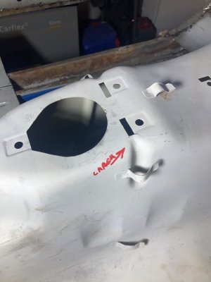
In red you can just make out the hairline crack. In green a weld already made by the PO... this is at the top of the tunnel, where a depression runs down both sides for the wiring harness to fall into.
View attachment 113621
and another detail of the cracks; when you look closely you can see that there are actually 3 hairline cracks coming from the speed clip opening running down the tunnel.
View attachment 113623

here's what i made to improve it. It now has 3 threaded bushes to accept the shifter console. It's inserted from under the body and then plug welded it into place:
View attachment 113624View attachment 113625
I will not know if it is strong enough to prevent it from buckling again, untill I drive it. that'll be another 2-3 years at my speed.

Another modification is this one (i've seen it on more restorations): the sills have a middle layer that is connected only to the outer layer (just 0,8 mm thick) by spotwelds. As such it does form s closed section, but only to thin sheet. It could benefit from connecting it directly to the inner sill which is 1,5 mm thickness).
Here you see the 'open' channel, before the outer sill is placed. (Left sill, looing towards front wheel. Inner sill 1,5 mm on right, middle sill 'floating' on the left. Closing this channel with some tabs will increase it's bending stiffness immensely.

View attachment 113626

These connections are best made at the lower b-pillar and lower C-pillar. Here's the pic of the lower C-pillar where the jack pick up point is now welded to the inner sill. and on the right pic you can see the b-pillar where i could have (should have ...) made the connection as well:
View attachment 113627 View attachment 113628

Another modification i did was under the rear seats, where the reinforcement plate sits that holds the big pin for the rear subframe. This reinforcement plate is only rigidly connected on one side to the inner sill with seams welds. the other side just is spotwelded to the 0.8 mm floor. In an ideal world, it should all be constructed in triangles. that is not the case here: the reinforcement just hangs on the wall of the inner sill, and the floor is not really strong. SO i opted to create another strong point for the reinforcement to be welded to.
In my car the floor under the the rear trailing arm pick-up points were rusted out, including the ends of the inner sill. So i needed to replace those sections anyway.
I made a new end section to the inner sill, with a larger flange that folds around the corner into the wheel well, just behind the reinforcement plate. It now connects directly to the reinforcement piece that sits under the rear seat, completing the 'triangle' to.
Gaping hole under rear right seat & New inner sill end section made (The flange in the green rectangle was my addition):

View attachment 113630 View attachment 113632

and lined up for welding:
View attachment 113631

and here you now see how it supports the reinforcement plate. IIt was plug welded together later on from this side, so not noticeable anymore afterwards. The section left of the red line was added, in comparision to OEM shape.

View attachment 113634

In the rear, i've reinforced the differential mount. As my trunk is quite airy at the moment; this was easy to do:
I doubled the vertical flange where the diff support is welded to:

View attachment 113635View attachment 113636
then spotwelded the whole thing. The thicker welds are where it connects to the rear diff mount.
View attachment 113637View attachment 113638

Now as you see, I haven't touched the front of my car. I need to open the hood still after 7 years working on the mid & rear of the car....
I have the same cracks coming from the speed clip opening running down the tunnel. I’m will do TIG Welding.
 

Attachments

  • IMG_4902.jpeg
    IMG_4902.jpeg
    434.9 KB · Views: 24
Back
Top